
ShockSense

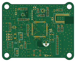
About the ShockSense PCB
ShockSense is an open source STM32 PCB design by Consultant-47, published on GitHub. It is a 2-layer board measuring 75.6 × 60.6 mm, with 89 components from 48 distinct parts.
Its main chip is the STM32L552VETxQ, from the STM32 family. Other key parts include the USBLC6-2SC6, MCP73833-xxx-UN, MIC5317-3.3xM5, ADXL372xx and LSM6DSV16BX. By type, the board carries 33 capacitors, 20 resistors, 14 connectors, 7 ICs, 7 diodes and 2 modules.
It belongs with the sensors and power & battery designs in this gallery.
From the project
1. BOOT0 Pin Not Pulled Down - The BOOT0 pin of the STM32L552VET6Q was left floating. - This can cause unpredictable behavior during power-up or prevent the MCU from booting from flash. - Workaround: Manually pull the BOOT0 pin low using an external resistor (10kΩ to GND).
1. BOOT0 Pin Not Pulled Down - The BOOT0 pin of the STM32L552VET6Q was left floating. - This can cause unpredictable behavior during power-up or prevent the MCU from booting from flash. - Workaround: Manually pull the BOOT0 pin low using an external resistor (10kΩ to GND).
2. Incorrect Silkscreen Labels - The silkscreen of the VDD and GND pins has been mistakenly exchanged for the bluetooth module, and the silkscreen for the battery charging indicator LEDs. - These errors do not affect electrical functionality but may lead to assembly confusion. - Refer to: Marked corrections in the PCB…
Main components on the ShockSense
ShockSense bill of materials (BOM)
89 components, 48 distinct parts — part numbers from the project's BOM.
| Qty | Part | Footprint | Refs |
|---|---|---|---|
| 1 | USBLC6-2SC6 | SOT-23-6 | U2 |
| 1 | MCP73833-xxx-UN | MSOP-10_3x3mm_P0.5mm | U3 |
| 1 | MIC5317-3.3xM5 | SOT-23-5 | U4 |
| 1 | ADXL372xx | ADXL372 | U5 |
| 1 | LSM6DSV16BX | LSM6DSV16BX_ST_6DOF_Temp | U6 |
| 1 | BGM113A256V2 | BGM113A256V2 | U7 |
| 1 | STM32L552VETxQ | LQFP-100_14x14mm_P0.5mm | U8 |
| 2 | SiA811ADJxx | Vishay_PowerPAK_SC70-6L_Dual | M1, M2 |
| 1 | LSE 32.768kHz | 830016178 | Y1 |
| 1 | HSE 32MHz | YSX211SL | Y2 |
| 1 | USB_C_Receptacle_USB2.0_16P | USB_C_Receptacle_GCT_USB4085 | J1 |
| 1 | Battery Conn | JST_EH_B2B-EH-A_1x02_P2.50mm_Vertical | J2 |
| 1 | SW Debug | PinHeader_1x05_P2.54mm_Vertical | J3 |
| 1 | SD Card Header | PinHeader_1x08_P2.54mm_Vertical | J4 |
| 1 | LSM2 | PinHeader_1x04_P2.54mm_Vertical | J5 |
| 1 | LSM1 | PinHeader_1x05_P2.54mm_Vertical | J6 |
| 1 | ADXL1 | PinHeader_1x04_P2.54mm_Vertical | J7 |
| 1 | CurrMeasure | PinHeader_1x03_P2.54mm_Vertical | J8 |
| 1 | ADXL2 | PinHeader_1x03_P2.54mm_Vertical | J9 |
| 1 | ADXL3 | PinHeader_1x02_P2.54mm_Vertical | J10 |
Show 28 more
| Qty | Part | Footprint | Refs |
|---|---|---|---|
| 1 | BLE1 | PinHeader_1x03_P2.54mm_Vertical | J11 |
| 1 | Therm Conn | JST_EH_B2B-EH-A_1x02_P2.50mm_Vertical | J12 |
| 1 | BLE2 | PinHeader_1x03_P2.54mm_Vertical | J13 |
| 1 | BLE3 | PinHeader_1x03_P2.54mm_Vertical | J15 |
| 1 | SW_SPDT | SW_Lock_DPDT_KFC-5.8C | SW1 |
| 1 | SW_Push | SW_PUSH_6mm | SW2 |
| 7 | LED | LED_0805_2012Metric | D1, D2, D3, D4, D5, D6, D7 |
| 1 | FB | L_0805_2012Metric_Pad1.15x1.40mm_HandSolder | FB1 |
| 1 | 4u7H | L_APV_ANR_WEL | L1 |
| 8 | 100nF | C_0603_1608Metric_Pad1.08x0.95mm_HandSolder | C1, C2, C3, C4, C5, C10, C16, C34 |
| 3 | 4u7F | C_0805_2012Metric_Pad1.18x1.45mm_HandSolder | C6, C12, C13 |
| 2 | 10nF | C_0603_1608Metric_Pad1.08x0.95mm_HandSolder | C7, C33 |
| 2 | 1uF | C_0603_1608Metric_Pad1.08x0.95mm_HandSolder | C8, C9 |
| 1 | 4u7F | C_0603_1608Metric_Pad1.08x0.95mm_HandSolder | C11 |
| 3 | 1uF | C_0805_2012Metric_Pad1.18x1.45mm_HandSolder | C14, C15, C28 |
| 2 | 8pF | C_0603_1608Metric_Pad1.08x0.95mm_HandSolder | C17, C18 |
| 2 | 15pF | C_0603_1608Metric_Pad1.08x0.95mm_HandSolder | C19, C20 |
| 8 | 100nF | C_0805_2012Metric_Pad1.18x1.45mm_HandSolder | C21, C22, C23, C24, C25, C26, C27, C31 |
| 1 | 10uF | C_0805_2012Metric_Pad1.18x1.45mm_HandSolder | C29 |
| 1 | 47uF | CP_Radial_D6.3mm_P2.50mm | C30 |
| 1 | 10k | R_0603_1608Metric_Pad0.98x0.95mm_HandSolder | R1 |
| 1 | 8k | R_0603_1608Metric_Pad0.98x0.95mm_HandSolder | R2 |
| 1 | 800R | R_0603_1608Metric_Pad0.98x0.95mm_HandSolder | R3 |
| 7 | 221R | R_0603_1608Metric_Pad0.98x0.95mm_HandSolder | R4, R5, R6, R15, R16, R17, R20 |
| 2 | 5k1 | R_0603_1608Metric_Pad0.98x0.95mm_HandSolder | R7, R8 |
| 6 | 47k | R_0603_1608Metric_Pad0.98x0.95mm_HandSolder | R9, R10, R11, R12, R13, R14 |
| 1 | approx 1k | R_0603_1608Metric_Pad0.98x0.95mm_HandSolder | R18 |
| 1 | >33k | R_0603_1608Metric_Pad0.98x0.95mm_HandSolder | R19 |
ShockSense design files
The KiCad project lives in the Consultant-47/ShockSense repository on GitHub; these links point at the commit this page was built from.
ShockSense: common questions
What microcontroller does the ShockSense use?
The ShockSense is built around the STM32L552VETxQ, from the STM32 family.
How big is the ShockSense PCB?
The ShockSense measures 75.6 × 60.6 mm, has 2 copper layers and is 1.6 mm thick.
How many components are on the ShockSense?
89 components, from 48 distinct parts, with part numbers taken from the project's own BOM. The full bill of materials is listed on this page.
Where can I download the ShockSense design files?
From the Consultant-47/ShockSense repository on GitHub, which has the KiCad layout, the schematic and the BOM; the links under Design files point to each one.
Can I use the ShockSense design in my own project?
The repository has no license, so all rights stay with Consultant-47. Use it as a reference, and ask the author before reusing the design.
Can I test firmware for the ShockSense without the hardware?
Yes. HardLabs builds a simulation of the board from its netlist and BOM, so you can run and debug STM32 firmware against it before you order a PCB.
Similar boards
 STM32
LumenPnP Motherboard
opulo-inc
149 × 95 mm296 parts4LCC-BY-SA-4.03.7k STM32
Type g
google
169 × 30 mm24 parts2LApache-2.02.9k STM32
Base
52.3 × 52.3 mm36 parts2LApache-2.02.9k STM32
Main panel
234 × 84 mm26 parts4LApache-2.02.9k STM32
Type a
150 × 30 mm14 parts2LApache-2.02.9k STM32
Type c
188 × 30 mm17 parts2LApache-2.02.9k