
Usb trace adapter


About the Usb trace adapter PCB
Usb trace adapter is an open source PCB design by daniel-starke, published on GitHub under the BSD-3-Clause license. It is a 2-layer board measuring 21 × 18.8 mm, with 3 components from 3 distinct parts.
It belongs with the test & measurement designs in this gallery.
From the project
Hardware adapter for USB tracing via logic analyzer.
The USB trace adapter can be used to trace/probe the USB communication of a USB low speed, high speed or full speed connection with a logic analyzer or oscilloscope.
The USB trace adapter is build up of a USB 2.0 type A receptacle and a USB 2.0 type A plug at both ends with a pin header in-between. All lines are passed through between receptacle and plug as it. The pin header offers easy access to VBUS, D+, D- and GND to allow tracing and probing.
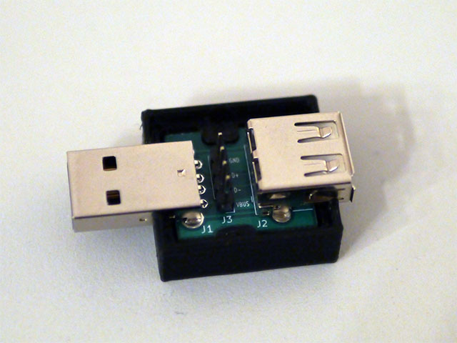
Usb trace adapter bill of materials (BOM)
3 components, 3 distinct parts.
| Qty | Part | Footprint | Refs |
|---|---|---|---|
| 1 | USB_A | USB_A_TH_AM90 | J1 |
| 1 | USB_A | USB_A_Stewart_SS-52100-001_Horizontal | J2 |
| 1 | Conn_01x04 | PinHeader_1x04_P2.54mm_Vertical | J3 |
Usb trace adapter design files
The KiCad project lives in the daniel-starke/usb-trace-adapter repository on GitHub; these links point at the commit this page was built from.
Usb trace adapter: common questions
How big is the Usb trace adapter PCB?
The Usb trace adapter measures 21 × 18.8 mm, has 2 copper layers and is 1.2 mm thick.
How many components are on the Usb trace adapter?
3 components, from 3 distinct parts. The full bill of materials is listed on this page.
Where can I download the Usb trace adapter design files?
From the daniel-starke/usb-trace-adapter repository on GitHub, which has the KiCad layout; the links under Design files point to each one.
Can I use the Usb trace adapter design in my own project?
Yes, under the terms of its BSD-3-Clause license, which daniel-starke chose for the repository.
Similar boards
LevelShifter
gusmanb
28.3 × 39.8 mm21 parts2LGPL-3.05.0k
StackLink
52.3 × 10.5 mm5 parts2LGPL-3.05.0k
AnalyzerBoxPCB fork
52.7 × 47.9 mm54 parts4LGPL-3.05.0k
EleLab v2 Bus100
Chrismettal
100 × 100 mm37 parts2LGPL-3.0528
EleLab v2 Bus150
150 × 50 mm37 parts2LGPL-3.0528
EleLab v2 PowerFeed
68 × 50 mm11 parts2LGPL-3.0528