
Dogooder
About the Dogooder PCB
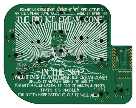
Dogooder is an open source PCB design by davidphilipbarr, published on GitHub. It is a 2-layer board measuring 113.9 × 88.9 mm, with 37 components from 7 distinct parts.
Other key parts include the SeeeduinoXIAO. By type, the board carries 17 switches, 17 diodes, 1 IC and 1 connector.
Main components on the Dogooder
Dogooder bill of materials (BOM)
37 components, 7 distinct parts.
| Qty | Part | Footprint | Refs |
|---|---|---|---|
| 1 | SeeeduinoXIAO | SeeeduinoXIAO-2.54-21X17.8MM-lpgala-holes-jumps | U1 |
| 1 | AudioJack4dpb | TRRS-PJ-DPB2 | J1 |
| 1 | SW_PUSH | SW_Push_SPST_NO_Alps_SKRK | RSW1 |
| 1 | SW_SPDT | SPDT_C128955 | SW2 |
| 16 | SW_PUSH | SW_PG1350_reversible_b2_v3 | SW3, SW4, SW5, SW6, SW8, SW9, SW10, SW11 +8 |
| 1 | D | D_1206_3216Metric | D1 |
| 16 | D | D_SOD-123F | D2, D3, D4, D5, D6, D7, D8, D9 +8 |
Dogooder design files
The KiCad project lives in the davidphilipbarr/testing-boards repository on GitHub; these links point at the commit this page was built from.
- Layoutoidarc/dogooder.kicad_pcb
- Schematicoidarc/dogooder.kicad_sch
Dogooder: common questions
How big is the Dogooder PCB?
The Dogooder measures 113.9 × 88.9 mm, has 2 copper layers and is 1.6 mm thick.
How many components are on the Dogooder?
37 components, from 7 distinct parts. The full bill of materials is listed on this page.
Where can I download the Dogooder design files?
From the davidphilipbarr/testing-boards repository on GitHub, which has the KiCad layout and the schematic; the links under Design files point to each one.
Can I use the Dogooder design in my own project?
The repository has no license, so all rights stay with davidphilipbarr. Use it as a reference, and ask the author before reusing the design.
More boards in testing-boards
Corne Light
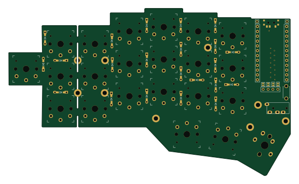
147.4 × 87.7 mm59 parts2LNo license10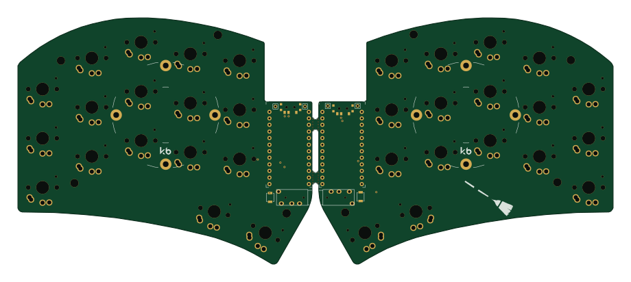
Sweep mid
229.5 × 95.2 mm45 parts2LNo license10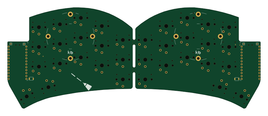
Sweepv2.1
216.9 × 86.9 mm44 parts2LNo license10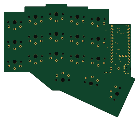
Chocorne36-n!n
112.9 × 97.1 mm26 parts2LNo license10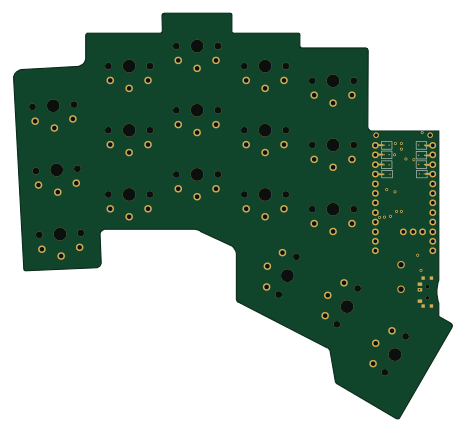
Demeter
116.2 × 107.4 mm22 parts2LNo license10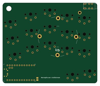
Hawk moth
98.4 × 83 mm21 parts2LNo license10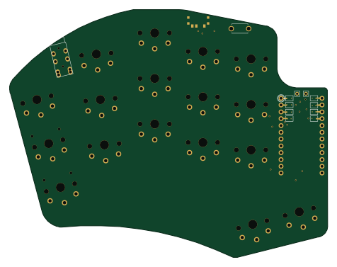
Hypergolic
118.8 × 92.6 mm21 parts2LNo license10
Flip
97.6 × 83 mm20 parts2LNo license10
Sweepv2 plate
105 × 86.9 mm17 parts2LNo license10
Sweep mid plate
112.1 × 95.2 mm17 parts2LNo license10