
Updi-Key

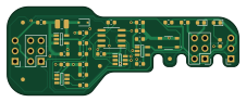
About the Updi-Key PCB
Updi-Key is an open source AVR/Arduino PCB design by Dlloydev, published on GitHub under the MIT license. It is a 2-layer board measuring 56.5 × 21.6 mm, with 32 components from 24 distinct parts.
Its main chip is the ATtiny202-SS, from the AVR/Arduino family. Other key parts include the NCP1406SNT1G and MIC2091-1YM5-TR. By type, the board carries 9 resistors, 8 capacitors, 4 connectors, 3 ICs, 3 switches and 2 LEDs.
It belongs with the usb & debug tools designs in this gallery.
From the project
This DIY open source hardware connects inline with any UPDI programmer to provide a HV UPDI programming solution for tinyAVR® 0/1/2 series MCUs. Compatible with UPDI programmers that operate with jtag2updi, avrdude, pyupdi, MPLAB X IDE, MPLAB X IPE, PlatformIO and Arduino IDE using any target voltage from 3 to 5V.
Updi-Key is an inline adapter that transforms your favorite UPDI programmer into a HV UPDI programmer. Now you can easily enable UPDI mode, program and power-cycle your target MCU to explore additional features like using the UPDI pin for LUT0, AIN0, GPIO or Reset.
To provide a tool that allows easy access to the additional functions of the programming pin, which becomes more important in low pin count applications. To enhance your existing programming solution with a convenient low cost adapter.
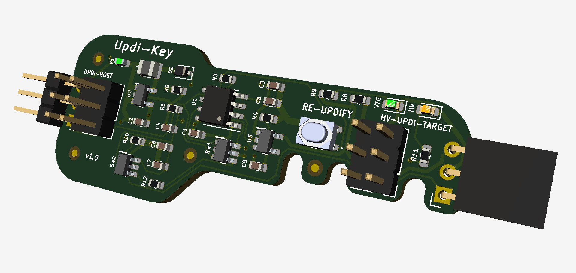
Main components on the Updi-Key
Updi-Key bill of materials (BOM)
32 components, 24 distinct parts.
| Qty | Part | Footprint | Refs |
|---|---|---|---|
| 1 | ATtiny202-SS | SOIC-8_3.9x4.9mm_P1.27mm | U1 |
| 1 | NCP1406SNT1G | SOT95P275X110-5N | U2 |
| 1 | MIC2091-1YM5-TR | SOT95P280X130-5N | U3 |
| 1 | UPDI-IN | PinHeader_1x03_P2.54mm_Horizontal | J2 |
| 1 | UPDI_IN6 | PinHeader_2x03_P2.54mm_Vertical | J3 |
| 1 | HVUPDI_OUT6 | PinHeader_2x03_P2.54mm_Vertical | J4 |
| 1 | HVUPDI-OUT | PinSocket_1x03_P2.54mm_Horizontal | J5 |
| 1 | 50mA | Fuse_0603_1608Metric | F1 |
| 1 | SN74LVC1G3157DBVR | SOT95P280X145-6N | SW1 |
| 1 | ISL43210IHZ-T | SOT95P280X145-6N | SW2 |
| 1 | PTS810SJG250SMTRLFS | PTS810SJG250SMTRLFS | SW3 |
| 1 | ORANGE | LED_0603_1608Metric | HV1 |
| 1 | GREEN | LED_0603_1608Metric | VTG1 |
| 1 | PMEG4005CEJX | D_SOD-323F | D2 |
| 1 | 47µH | L_1008_2520Metric | L1 |
| 3 | 0.1µF | C_0603_1608Metric | C1, C7, C8 |
| 3 | 10µF | C_0603_1608Metric | C2, C3, C5 |
| 1 | 68pF | C_0603_1608Metric | C4 |
| 1 | 4.7µF | C_0603_1608Metric | C6 |
| 3 | 10K | R_0603_1608Metric | R3, R4, R10 |
Show 4 more
| Qty | Part | Footprint | Refs |
|---|---|---|---|
| 1 | 102K 1% | R_0603_1608Metric | R5 |
| 1 | 11K 1% | R_0603_1608Metric | R6 |
| 2 | 1K | R_0603_1608Metric | R8, R9 |
| 2 | 180Ω | R_0603_1608Metric | R11, R12 |
Updi-Key design files
The KiCad project lives in the Dlloydev/Updi-Key repository on GitHub; these links point at the commit this page was built from.
Updi-Key: common questions
What microcontroller does the Updi-Key use?
The Updi-Key is built around the ATtiny202-SS, from the AVR/Arduino family.
How big is the Updi-Key PCB?
The Updi-Key measures 56.5 × 21.6 mm, has 2 copper layers and is 1.6 mm thick.
How many components are on the Updi-Key?
32 components, from 24 distinct parts. The full bill of materials is listed on this page.
Where can I download the Updi-Key design files?
From the Dlloydev/Updi-Key repository on GitHub, which has the KiCad layout; the links under Design files point to each one.
Can I use the Updi-Key design in my own project?
Yes, under the terms of its MIT license, which Dlloydev chose for the repository.
Can I test firmware for the Updi-Key without the hardware?
Yes. HardLabs builds a simulation of the board from its netlist and BOM, so you can run and debug AVR/Arduino firmware against it before you order a PCB.
Similar boards
 AVR/Arduino
Magspoof
samyk
35 × 29 mm11 parts2LNo license4.2k AVR/Arduino
Redox keyboard
mattdibi
162.2 × 126.5 mm77 parts2LMIT2.0k AVR/Arduino
Labrador
espotek-org
36.8 × 34.7 mm75 parts2LNo license1.2k AVR/Arduino
V4
stuartpittaway
30 × 50 mm38 parts2LCC-BY-NC-4.01.1k AVR/Arduino
ModuleV450
30 × 61.4 mm39 parts2LCC-BY-NC-4.01.1k AVR/Arduino
Discipline
coseyfannitutti
304.9 × 122.8 mm170 parts2LCC-BY-NC-4.01.0k