
Stm32-debug board

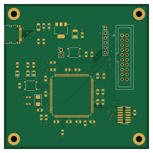
About the Stm32-debug board
Stm32-debug board is an open source STM32 PCB design by ericdwatson, published on GitHub under the Custom license license. It is a 2-layer board measuring 75 × 75 mm, with 50 components from 25 distinct parts.
Its main chip is the STM32F446ZETX, from the STM32 family. Other key parts include the AMS1117-3.3. By type, the board carries 26 capacitors, 10 resistors, 5 connectors, 3 diodes, 2 ICs and 2 switches.
It belongs with the dev boards & breakouts and usb & debug tools designs in this gallery.
From the project
Open-source STM32F446ZE development board featuring SWD, JTAG, STDC14, SWO trace and UART debugging, with KiCad hardware designs and STM32CubeIDE example firmware.
A custom STM32F446ZE development board (hardware revision V1.0) designed for embedded software development, hardware debugging and testing.
Hardware status: V1.0 successfully manufactured and functionally validated, including standalone operation at 180 MHz. No corrective PCB rework was required during the planned bench tests.
The intent behind this project was to generate a board with three commonly used STM32 programming/debugging interfaces and verify that all work correctly. I used an STM32F446ZE because I want to use this part on a separate project, so wanted to create a test board…
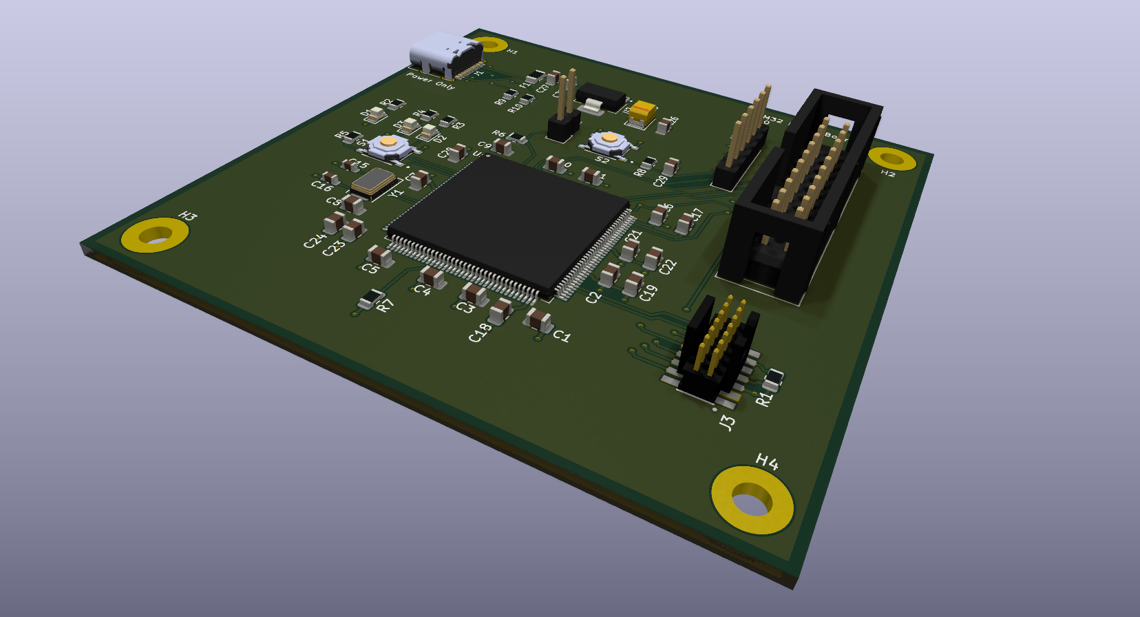
Main components on the Stm32-debug board
Stm32-debug board bill of materials (BOM)
50 components, 25 distinct parts — part numbers from the project's BOM.
| Qty | Part | Footprint | Refs |
|---|---|---|---|
| 1 | STM32F446ZETX STM32F446ZETx | LQFP-144_20x20mm_P0.5mm | U1 |
| 1 | AMS1117-3.3 | SOT-223-3_TabPin2 | U2 |
| 1 | X50328MSB2GI 8 MHz YXC | Crystal_SMD_5032-2Pin_5.0x3.2mm | Y1 |
| 1 | TYPE-C-31-M-12 Korean Hroparts Elec | USB_C_Receptacle_HRO_TYPE-C-31-M-12 | J1 |
| 1 | TST-110-01-G-D Conn_02x10_Odd_Even Samtec | IDC-Header_2x10_P2.54mm_Vertical | J2 |
| 1 | FTSH-107-01-L-DV-K-A Samtec | SAMTEC_FTSH-107-01-L-DV-K-A | J3 |
| 1 | TSW-106-07-G-S Conn_01x06 Samtec | PinHeader_1x06_P2.54mm_Vertical | J4 |
| 1 | Conn_01x02 Samtec | PinHeader_1x02_P2.54mm_Vertical | J5 |
| 1 | 500mA/24V 500mA DOWO | Fuse_1206_3216Metric | F1 |
| 1 | TS-1187A-B-A-B User Button XKB Industrial Precision | SW_TS-1187A-B-A-B | S1 |
| 1 | TS-1187A-B-A-B Reset Button XKB Industrial Precision | SW_TS-1187A-B-A-B | S2 |
| 1 | KT-0805Y PWR Hubei KENTO Electronics | LED_0805_2012Metric | D1 |
| 1 | KT-0805Y LED1 Hubei KENTO Electronics | LED_0805_2012Metric | D2 |
| 1 | KT-0805Y LED2 Hubei KENTO Electronics | LED_0805_2012Metric | D3 |
| 17 | 100NF 100nF | C_0805_2012Metric | C1, C2, C3, C4, C5, C6, C7, C8 +9 |
| 2 | 0603CG300J500NT 30pF FH (Guangdong Fenghua Advanced Tech) | C_0603_1608Metric | C15, C16 |
| 2 | 2.2UF 2.2uF | C_0805_2012Metric | C17, C18 |
| 1 | CL21A475KAQNNNE 4.7uF | C_0805_2012Metric | C19 |
| 2 | 1UF 1uF | C_0805_2012Metric | C22, C24 |
| 1 | CL21A226MAQNNNE 22uF | C_0805_2012Metric | C27 |
Show 5 more
| Qty | Part | Footprint | Refs |
|---|---|---|---|
| 1 | TAJB226K010RNJ 22uF | CP_EIA-3528-21_Kemet-B | C28 |
| 1 | 0805W8F1000T5E 100R UNI-ROYAL | R_0805_2012Metric | R1 |
| 3 | 0805W8F1001T5E 1K UNI-ROYAL | R_0805_2012Metric | R2, R3, R4 |
| 4 | 0805W8F1002T5E 10K UNI-ROYAL | R_0805_2012Metric | R5, R6, R7, R8 |
| 2 | 0805W8F5101T5E 5.1K UNI-ROYAL | R_0805_2012Metric | R9, R10 |
Stm32-debug board design files
The KiCad project lives in the ericdwatson/stm32-debug-board repository on GitHub; these links point at the commit this page was built from.
Stm32-debug board: common questions
What microcontroller does the Stm32-debug board use?
The Stm32-debug board is built around the STM32F446ZETX, from the STM32 family.
How big is the Stm32-debug board?
The Stm32-debug board measures 75 × 75 mm, has 2 copper layers and is 1.6 mm thick.
How many components are on the Stm32-debug board?
50 components, from 25 distinct parts, with part numbers taken from the project's own BOM. The full bill of materials is listed on this page.
Where can I download the Stm32-debug board design files?
From the ericdwatson/stm32-debug-board repository on GitHub, which has the KiCad layout, the schematic and the BOM; the links under Design files point to each one.
Can I use the Stm32-debug board design in my own project?
It is published under Custom license, which limits how it may be reused; read the license before building on it.
Can I test firmware for the Stm32-debug board without the hardware?
Yes. HardLabs builds a simulation of the board from its netlist and BOM, so you can run and debug STM32 firmware against it before you order a PCB.
Similar boards
 STM32
LumenPnP Motherboard
opulo-inc
149 × 95 mm296 parts4LCC-BY-SA-4.03.7k STM32
Type g
google
169 × 30 mm24 parts2LApache-2.02.9k STM32
Type a
150 × 30 mm14 parts2LApache-2.02.9k STM32
Base
52.3 × 52.3 mm36 parts2LApache-2.02.9k STM32
Main panel
234 × 84 mm26 parts4LApache-2.02.9k STM32
Type c
188 × 30 mm17 parts2LApache-2.02.9k