
Astable-555-timer

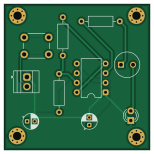
About the Astable-555-timer PCB
Astable-555-timer is an open source PCB design by EsdrasMukuku, published on GitHub. It is a 2-layer board measuring 38.5 × 38.5 mm, with 10 components from 10 distinct parts.
Other key parts include the ICM7555XP. By type, the board carries 3 resistors, 2 capacitors, 1 IC, 1 connector, 1 buzzer and 1 switch.
From the project
a simple LED flasher with buzzer controled by an astable 555timer
- 📍 Overview - 👾 Features - 🔌 How It Works - 🖼 Design Files - 📁 Project Structure - 📂 Project Index - 🚀 Getting Started - ☑️ Prerequisites - ⚙️ Installation - 🤖 Usage - 📌 Project Roadmap - 🔰 Contributing - 🎗 License - 🙌 Acknowledgments
astable-555-timer is a small open-source hardware project: an LED flasher with a buzzer, controlled by a 555 timer running in astable mode. The timer free-runs as an oscillator, so the LED blinks and the buzzer beeps on their own, with no microcontroller or code required. A momentary push button powers the circuit, and power comes in through a screw terminal.…
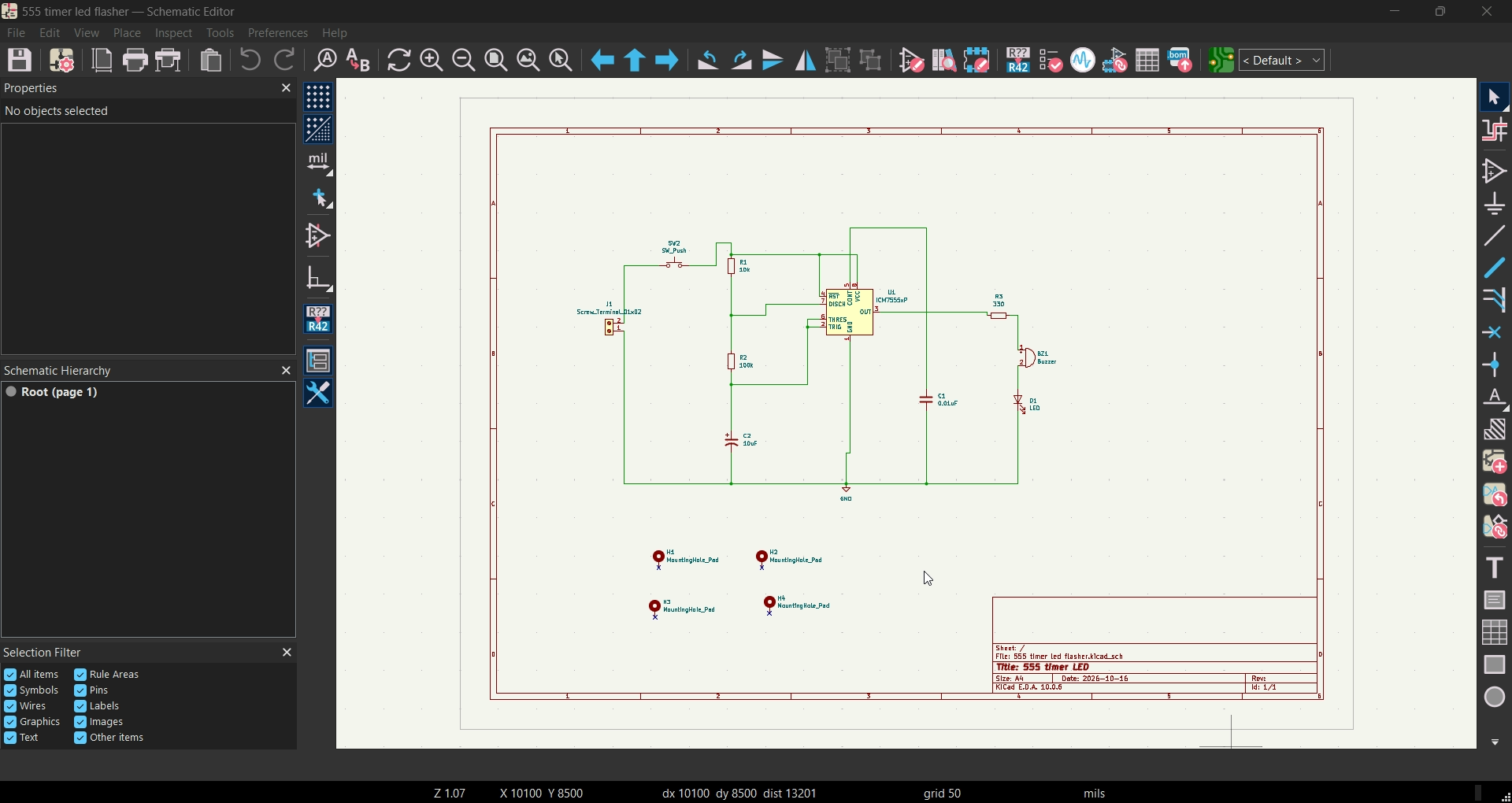
Main components on the Astable-555-timer
Astable-555-timer bill of materials (BOM)
10 components, 10 distinct parts — part numbers from the project's BOM.
| Qty | Part | Footprint | Refs |
|---|---|---|---|
| 1 | ICM7555XP ICM7555xP | DIP-8_W7.62mm | U1 |
| 1 | SCREW_TERMINAL_01X02 Screw_Terminal_01x02 | TerminalBlock_Xinya_XY308-2.54-2P_1x02_P2.54mm_Horizontal | J1 |
| 1 | Buzzer | MagneticBuzzer_Kingstate_KCG0601 | BZ1 |
| 1 | SW_Push | SW_PUSH_6mm | SW2 |
| 1 | LED | LED_D3.0mm | D1 |
| 1 | 0.01UF 0.01uF | CP_Radial_D4.0mm_P2.00mm | C1 |
| 1 | 10UF 10uF | CP_Radial_D4.0mm_P2.00mm | C2 |
| 1 | 10K 10k | R_Axial_DIN0207_L6.3mm_D2.5mm_P10.16mm_Horizontal | R1 |
| 1 | 100K 100k | R_Axial_DIN0207_L6.3mm_D2.5mm_P10.16mm_Horizontal | R2 |
| 1 | 330 | R_Axial_DIN0207_L6.3mm_D2.5mm_P10.16mm_Horizontal | R3 |
Astable-555-timer design files
The KiCad project lives in the EsdrasMukuku/astable-555-timer repository on GitHub; these links point at the commit this page was built from.
Astable-555-timer: common questions
How big is the Astable-555-timer PCB?
The Astable-555-timer measures 38.5 × 38.5 mm, has 2 copper layers and is 1.6 mm thick.
How many components are on the Astable-555-timer?
10 components, from 10 distinct parts, with part numbers taken from the project's own BOM. The full bill of materials is listed on this page.
Where can I download the Astable-555-timer design files?
From the EsdrasMukuku/astable-555-timer repository on GitHub, which has the KiCad layout, the schematic and the BOM; the links under Design files point to each one.
Can I use the Astable-555-timer design in my own project?
The repository has no license, so all rights stay with EsdrasMukuku. Use it as a reference, and ask the author before reusing the design.