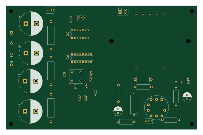
Anderson crt

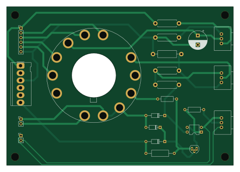
About the Anderson crt PCB
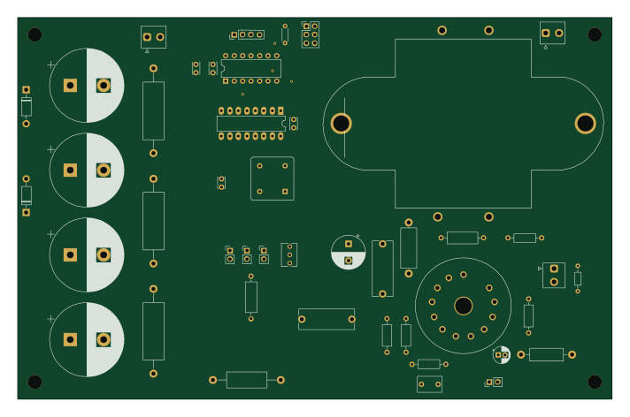
Anderson crt is an open source PCB design by eshazen, published on GitHub. It is a 2-layer board measuring 121.9 × 85.1 mm, with 22 components from 20 distinct parts.
Other key parts include the 6SN7. By type, the board carries 8 resistors, 4 connectors, 3 diodes, 1 IC, 1 transistor and 1 capacitor.
From the project
OK, time to jump on the oscilloscope clock bandwagon! It's an old idea, but they just look so cool.
OK, time to jump on the oscilloscope clock bandwagon! It's an old idea, but they just look so cool.
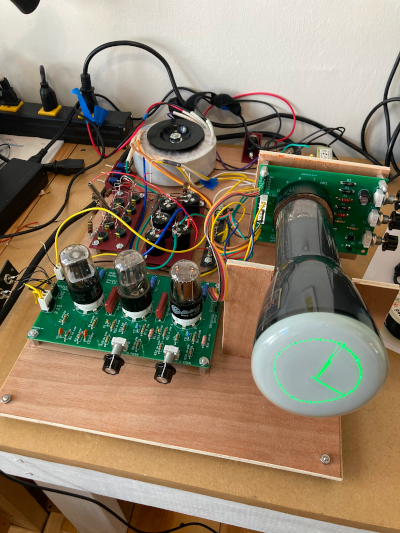
This was going to be a simple clone of some rather simplistic transistor-based designs around the internet, but now I've got something more ambitious in mind! Here's the prototype in action:
3BP1(A) CRT with proper drive to +360/-1400V pcb Tube-based deflection circuit using 6SN7 or 12SN7 dual triodes pcb Voltage-multiplier HV supply using an Antek transformer Display-list based vector graphics generator (or could cheat and use a uC)
Main components on the Anderson crt
Anderson crt bill of materials (BOM)
22 components, 20 distinct parts — part numbers from the project's BOM.
| Qty | Part | Footprint | Refs |
|---|---|---|---|
| 1 | 6SN7 PS2561 | DIP-4_W7.62mm | U1 |
| 1 | KSA1013YTA | TO-92_HandSolder | Q1 |
| 1 | CONN_01X02 Conn_01x06 | Molex_KK-396_5273-06A_1x06_P3.96mm_Vertical | J1 |
| 1 | CONN_01X04 Conn_01x02 | PinHeader_1x02_P2.54mm_Vertical | J2 |
| 1 | CONN_01X03 Conn_01x06 | PinHeader_1x06_P2.54mm_Vertical | J3 |
| 1 | CONN_01X06 Conn_01x02 | PinHeader_1x02_P2.54mm_Vertical | J4 |
| 1 | 3BP1(A) | B14_diheptal | CRT1 |
| 1 | 25K 100k | Potentiometer_Vishay_148-149_Single_Horizontal | RV1 |
| 1 | 25K 1M | Potentiometer_Vishay_148-149_Single_Horizontal | RV2 |
| 1 | 5k | Potentiometer_Vishay_148-149_Single_Horizontal | RV3 |
| 1 | 5.1V 400mW | D_DO-35_SOD27_P10.16mm_Horizontal | D1 |
| 1 | 1N914 | D_DO-35_SOD27_P7.62mm_Horizontal | D2 |
| 1 | 75v 400mW | D_DO-35_SOD27_P10.16mm_Horizontal | D3 |
| 1 | 10uF 400V | CP_Radial_D10.0mm_P5.00mm | C1 |
| 1 | 3.3k | R_Axial_DIN0207_L6.3mm_D2.5mm_P10.16mm_Horizontal | R1 |
| 1 | 47k | R_Axial_DIN0309_L9.0mm_D3.2mm_P15.24mm_Horizontal | R2 |
| 3 | 68k 1/2W | R_Axial_DIN0411_L9.9mm_D3.6mm_P12.70mm_Horizontal | R3, R4, R6 |
| 1 | 470k 2W | R_Axial_DIN0411_L9.9mm_D3.6mm_P15.24mm_Horizontal | R5 |
| 1 | 220k 2W | R_Axial_DIN0411_L9.9mm_D3.6mm_P12.70mm_Horizontal | R7 |
| 1 | 1k | R_Axial_DIN0207_L6.3mm_D2.5mm_P10.16mm_Horizontal | R8 |
Anderson crt design files
The KiCad project lives in the eshazen/scope-clock repository on GitHub; these links point at the commit this page was built from.
Anderson crt: common questions
How big is the Anderson crt PCB?
The Anderson crt measures 121.9 × 85.1 mm, has 2 copper layers and is 1.6 mm thick.
How many components are on the Anderson crt?
22 components, from 20 distinct parts, with part numbers taken from the project's own BOM. The full bill of materials is listed on this page.
Where can I download the Anderson crt design files?
From the eshazen/scope-clock repository on GitHub, which has the KiCad layout, the schematic and the BOM; the links under Design files point to each one.
Can I use the Anderson crt design in my own project?
The repository has no license, so all rights stay with eshazen. Use it as a reference, and ask the author before reusing the design.