Atari 2600 SECAM to RGB


About the Atari 2600 SECAM to RGB PCB
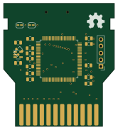
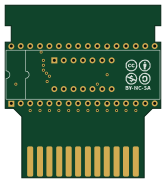
Atari 2600 SECAM to RGB is an open source PCB design by f1ac0, published on GitHub. It is a 2-layer board measuring 20.3 × 24.1 mm, with 33 components from 22 distinct parts.
Other key parts include the 74HCT08. By type, the board carries 21 test points, 8 resistors, 2 capacitors, 1 IC and 1 diode.
From the project
Atari 2600 replacement parts and expansions
While waiting for the system to dry after a complete clean and rust removal I found the useful projects below to help me start with this system I didn't know anything about. - First I needed some game so I put together a ROM cartridge on a breadboard and created a PCB from it. - Then not a single TV receiver I had could tune the video and audio signals correctly, but a BT848 PCTV PCI card. The mod by Eddy Foucault worked perfectly, I made my own version with CMS components and 5v only. - At last I removed the regulator to power the console from a modern 5V power source.
Main components on the Atari 2600 SECAM to RGB
Atari 2600 SECAM to RGB bill of materials (BOM)
33 components, 22 distinct parts.
| Qty | Part | Footprint | Refs |
|---|---|---|---|
| 1 | 74HCT08 | SO-14_3.9x8.65mm_P1.27mm | U1 |
| 1 | Blue | TestPoint_THTPad_D1.7mm_Drill1.0mm | TP1 |
| 1 | Green | TestPoint_THTPad_D1.7mm_Drill1.0mm | TP2 |
| 1 | Red | TestPoint_THTPad_D1.7mm_Drill1.0mm | TP3 |
| 1 | Sync | TestPoint_THTPad_D1.7mm_Drill1.0mm | TP4 |
| 2 | Audio | TestPoint_THTPad_D1.7mm_Drill1.0mm | TP5, TP6 |
| 1 | CR | TestPoint_THTPad_D1.7mm_Drill1.0mm | TP7 |
| 1 | CL | TestPoint_THTPad_D1.7mm_Drill1.0mm | TP8 |
| 6 | GND | TestPoint_THTPad_D1.7mm_Drill1.0mm | TP9, TP10, TP18, TP19, TP20, TP21 |
| 1 | TIA_Blue | TestPoint_THTPad_D1.7mm_Drill1.0mm | TP11 |
| 1 | TIA_Green | TestPoint_THTPad_D1.7mm_Drill1.0mm | TP12 |
| 1 | TIA_Red | TestPoint_THTPad_D1.7mm_Drill1.0mm | TP13 |
| 1 | TIA_CSync | TestPoint_THTPad_D1.7mm_Drill1.0mm | TP14 |
| 1 | TIA_Audio | TestPoint_THTPad_D1.7mm_Drill1.0mm | TP15 |
| 1 | 5V | TestPoint_THTPad_D1.7mm_Drill1.0mm | TP16 |
| 1 | 12V | TestPoint_THTPad_D1.7mm_Drill1.0mm | TP17 |
| 1 | Zener 2.7V | D_0805_2012Metric | D1 |
| 1 | 100nF | C_0805_2012Metric | C1 |
| 1 | 47uF 6.3V | CP_Elec_6.3x5.4 | C2 |
| 5 | 470 | R_0805_2012Metric | R1, R2, R3, R4, R7 |
Show 2 more
| Qty | Part | Footprint | Refs |
|---|---|---|---|
| 2 | 1k | R_0805_2012Metric | R5, R6 |
| 1 | 200 | R_0805_2012Metric | R8 |
Atari 2600 SECAM to RGB design files
The KiCad project lives in the f1ac0/Atari2600 repository on GitHub; these links point at the commit this page was built from.
Atari 2600 SECAM to RGB: common questions
How big is the Atari 2600 SECAM to RGB PCB?
The Atari 2600 SECAM to RGB measures 20.3 × 24.1 mm, has 2 copper layers and is 1.6 mm thick.
How many components are on the Atari 2600 SECAM to RGB?
33 components, from 22 distinct parts. The full bill of materials is listed on this page.
Where can I download the Atari 2600 SECAM to RGB design files?
From the f1ac0/Atari2600 repository on GitHub, which has the KiCad layout and the schematic; the links under Design files point to each one.
Can I use the Atari 2600 SECAM to RGB design in my own project?
The repository has no license, so all rights stay with f1ac0. Use it as a reference, and ask the author before reusing the design.