
Codex cad electronics lab

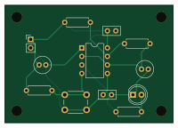
About the Codex cad electronics lab PCB
Codex cad electronics lab is an open source PCB design by finnandreh, published on GitHub under the MIT license. It is a 2-layer board measuring 50 × 35 mm, with 12 components from 10 distinct parts.
Other key parts include the TLC555CP. By type, the board carries 4 capacitors, 4 resistors, 1 IC, 1 connector, 1 switch and 1 diode.
From the project
Sanitized FreeCAD and KiCad source, exports, checks and videos from Finn Andre Hotvedt's Codex-assisted CAD lab.
An editable KiCad 7 prototype built from scratch around a TLC555CP CMOS timer in an astable configuration. The output drives a red LED through 1 kΩ and the board includes a reset pushbutton, supply/control decoupling and four M3 mounting holes.
- regulated input: 5 V at J1 (pin 1 +5 V, pin 2 GND); - timer: TLC555CP, PDIP-8; - nominal frequency: 0.686 Hz; - nominal duty cycle: 52.4%; - PCB: 50 × 35 × 1.6 mm, two copper layers; - 12 electrical components and four 3.2 mm non-plated mounting holes; - requested minimum clearance: 0.25 mm; - track width: 0.30 mm; - via: 0.60/0.30 mm.
Main components on the Codex cad electronics lab
Codex cad electronics lab bill of materials (BOM)
12 components, 10 distinct parts — part numbers from the project's BOM.
| Qty | Part | Footprint | Refs |
|---|---|---|---|
| 1 | TLC555CP | DIP-8_W7.62mm | U1 |
| 1 | 5V INPUT | PinHeader_1x02_P2.54mm_Vertical | J1 |
| 1 | RESET | SW_PUSH_6mm | SW1 |
| 1 | RED LED | LED_D5.0mm | D1 |
| 2 | 10uF 16V | C_Radial_D5.0mm_H11.0mm_P2.00mm | C1, C4 |
| 1 | 100NF 100nF | C_Disc_D5.0mm_W2.5mm_P2.50mm | C2 |
| 1 | 10NF 10nF | C_Disc_D5.0mm_W2.5mm_P2.50mm | C3 |
| 2 | 10K 10k | R_Axial_DIN0207_L6.3mm_D2.5mm_P7.62mm_Horizontal | R1, R4 |
| 1 | 100K 100k | R_Axial_DIN0207_L6.3mm_D2.5mm_P7.62mm_Horizontal | R2 |
| 1 | 1k | R_Axial_DIN0207_L6.3mm_D2.5mm_P7.62mm_Horizontal | R3 |
Codex cad electronics lab design files
The KiCad project lives in the finnandreh/codex-cad-electronics-lab repository on GitHub; these links point at the commit this page was built from.
Codex cad electronics lab: common questions
How big is the Codex cad electronics lab PCB?
The Codex cad electronics lab measures 50 × 35 mm, has 2 copper layers and is 1.6 mm thick.
How many components are on the Codex cad electronics lab?
12 components, from 10 distinct parts, with part numbers taken from the project's own BOM. The full bill of materials is listed on this page.
Where can I download the Codex cad electronics lab design files?
From the finnandreh/codex-cad-electronics-lab repository on GitHub, which has the KiCad layout, the schematic and the BOM; the links under Design files point to each one.
Can I use the Codex cad electronics lab design in my own project?
Yes, under the terms of its MIT license, which finnandreh chose for the repository.