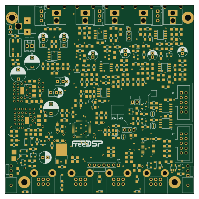
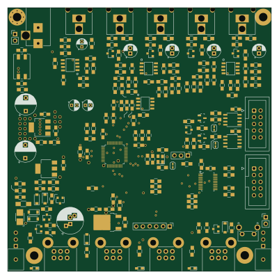
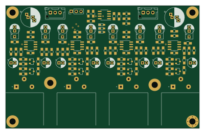
BalancedDriverBoard

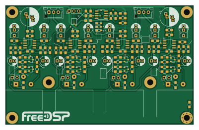
About the BalancedDriverBoard PCB
BalancedDriverBoard is an open source PCB design by freeDSP, published on GitHub under the CC0-1.0 license. It is a 2-layer board measuring 100 × 63.5 mm, with 126 components from 38 distinct parts.
Other key parts include the OPA1611. By type, the board carries 55 resistors, 44 capacitors, 11 connectors, 8 transistors, 5 ICs and 3 diodes.
From the project
A mono contruction Differntial 1 Input 4 output ADAU1701 DSP board, 96kHz TDM8 interlink is available.
A dual mono construction Concept Differential ADC 1 in 4 out ADAU1701 board. Extreme High performance (ADC to DAC Overall Distortion 0.00087%) differential A/D Conversion, differential RCA-pin Outputs, fs=96kHz, 8 slots TDM-Interlink across the boards.
- 1in 4 out RCA jacks on each PCB (2 boards requires for stereo use) - High-performance differential monaural ADAU1701 ADC circuit - GND lift-able Differntial RCA-pin Input curcuit - GND lift-able Differential RCA-pin Output circuit - Mains Power Switch - Power-ON/OFF/Reboot Anti-Pop Audio Mute - LED Power Indicator - MP1/MP7 controlled LED…
Main components on the BalancedDriverBoard
BalancedDriverBoard bill of materials (BOM)
126 components, 38 distinct parts — part numbers from the project's BOM.
| Qty | Part | Footprint | Refs |
|---|---|---|---|
| 5 | OPA1611 | SOIC-8_3.9x4.9mm_P1.27mm | U1, U2, U3, U4, U5 |
| 8 | 2SC3326 | SOT-23 | Q1, Q2, Q3, Q4, Q5, Q6, Q7, Q8 |
| 1 | CONN_01X02 B3B-EH | JST_XH_B3B-XH-AM_1x03_P2.50mm_Vertical | J1 |
| 1 | B3B-EH | JST_XH_B3B-XH-AM_1x03_P2.50mm_Vertical | J2 |
| 1 | CONN_02X5_ODD_EVEN PD3MRMS2 | SWITCHCRAFT_PD3MRMS2 | J3 |
| 3 | PD3MRMS2 | SWITCHCRAFT_PD3MRMS2 | J4, J5, J6 |
| 1 | CONN_01X07_MALE Conn_01x03 | PinHeader_1x03_P2.54mm_Vertical | J7 |
| 1 | PinHeader_01x02 | PinHeader_1x02_P2.54mm_Vertical | J8 |
| 1 | CONN_POWER_2.1MM PinHeader_01x02 | PinHeader_1x02_P2.54mm_Vertical | J9 |
| 1 | CONN_01X02 PinHeader_01x02 | PinHeader_1x02_P2.54mm_Vertical | J10 |
| 1 | HEADERPIN_01X03 PinHeader_01x02 | PinHeader_1x02_P2.54mm_Vertical | J11 |
| 3 | LED_GRN | LED_0603_HandSoldering | D1, D2, D3 |
| 7 | 2.2uF/16 | CP_Combo_D5.0mm_P2-5mm | C1, C2, C3, C5, C6, C7, C8 |
| 1 | 10U/16V 2.2uF/16 | CP_Combo_D5.0mm_P2-5mm | C4 |
| 1 | 10U/16V 10u/25V | C_0805_HandSoldering | C9 |
| 3 | 10u/25V | C_0805_HandSoldering | C10, C11, C12 |
| 1 | 47UF/6.3 100n | C_0805_HandSoldering | C13 |
| 1 | 2.2UF/16 100n | C_0805_HandSoldering | C14 |
| 2 | 100n | C_0805_HandSoldering | C15, C16 |
| 10 | 100pF | C_0805_HandSoldering | C17, C18, C19, C20, C21, C24, C25, C26 +2 |
Show 18 more
| Qty | Part | Footprint | Refs |
|---|---|---|---|
| 1 | 47UF/6.3 100pF | C_0805_HandSoldering | C22 |
| 1 | 10U/16V 100pF | C_0805_HandSoldering | C23 |
| 7 | 10u/16V | CP_Radial_D5.0mm_P2.00mm | C29, C30, C31, C32, C34, C35, C36 |
| 1 | 10U/16V 10u/16V | CP_Radial_D5.0mm_P2.00mm | C33 |
| 3 | 0.1uF | C_0805_HandSoldering | C37, C40, C44 |
| 1 | 220U 1uF | C_0805_HandSoldering | C38 |
| 1 | 220U 10u/25V | C_0805_HandSoldering | C39 |
| 2 | 330uF/16V | CP_Radial_D10.0mm_P2.50mm_P5.00mm | C41, C43 |
| 1 | 10uF | C_0805_HandSoldering | C42 |
| 8 | 10k | R_0805_HandSoldering | R1, R2, R3, R4, R5, R6, R7, R8 |
| 4 | 4.7k | R_0805_HandSoldering | R9, R11, R13, R15 |
| 4 | 20k | R_0805_HandSoldering | R10, R12, R14, R16 |
| 8 | 620R | R_0805_HandSoldering | R17, R18, R19, R20, R21, R22, R23, R24 |
| 8 | 22k | R_0805_HandSoldering | R25, R26, R27, R28, R29, R30, R31, R32 |
| 8 | 680R | R_0805_HandSoldering | R33, R34, R35, R36, R37, R38, R39, R40 |
| 10 | 47k | R_0805_HandSoldering | R41, R42, R43, R44, R45, R46, R47, R48 +2 |
| 1 | 1k | R_0805_HandSoldering | R49 |
| 4 | 22R | R_0805_HandSoldering | R52, R53, R54, R55 |
BalancedDriverBoard design files
The KiCad project lives in the freeDSP/FreeDSP_Catamaran_AB repository on GitHub; these links point at the commit this page was built from.
BalancedDriverBoard: common questions
How big is the BalancedDriverBoard PCB?
The BalancedDriverBoard measures 100 × 63.5 mm, has 2 copper layers and is 1.6 mm thick.
How many components are on the BalancedDriverBoard?
126 components, from 38 distinct parts, with part numbers taken from the project's own BOM. The full bill of materials is listed on this page.
Where can I download the BalancedDriverBoard design files?
From the freeDSP/FreeDSP_Catamaran_AB repository on GitHub, which has the KiCad layout and the BOM; the links under Design files point to each one.
Can I use the BalancedDriverBoard design in my own project?
Yes, under the terms of its CC0-1.0 license, which freeDSP chose for the repository.