EQ Driver V1.0

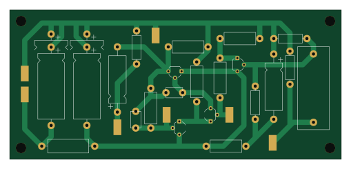
About the EQ Driver V1.0 PCB
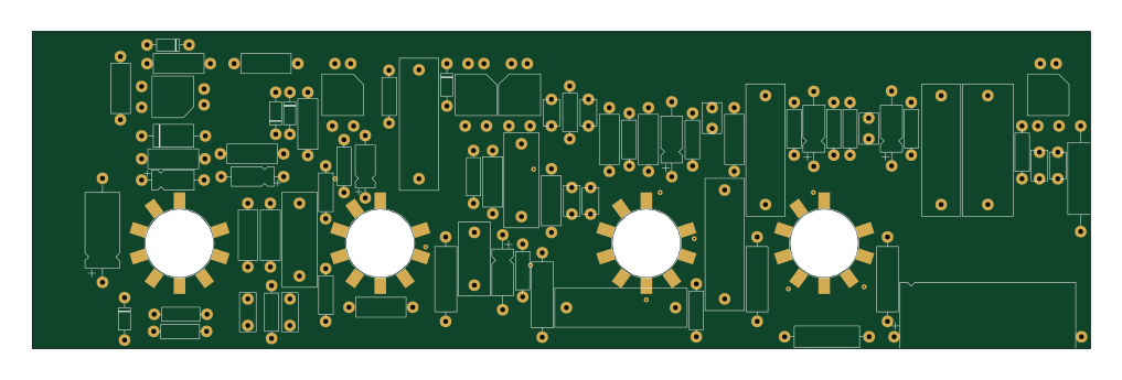
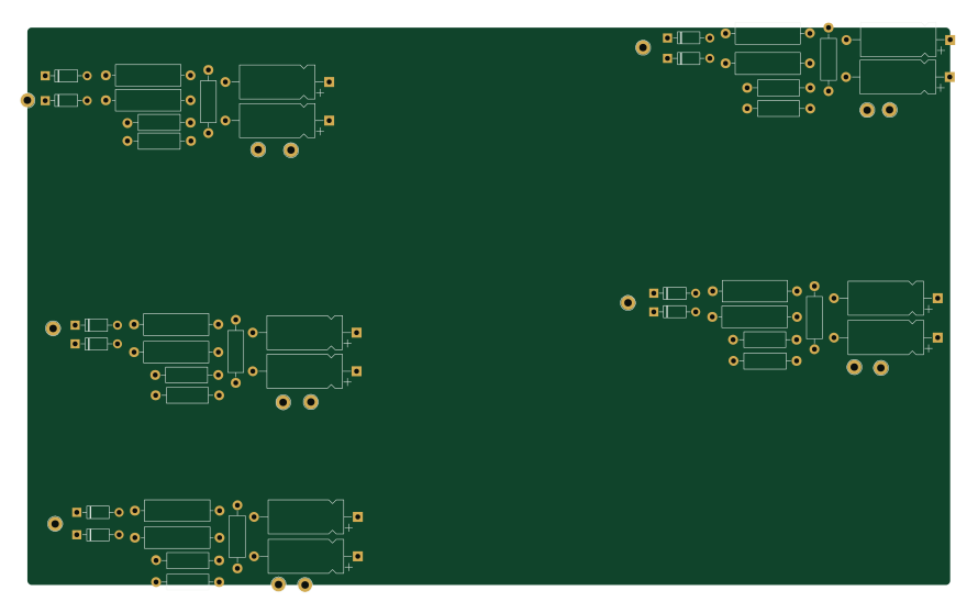
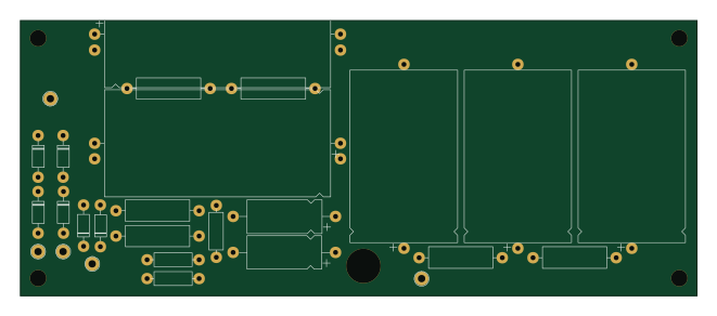
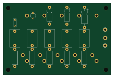
EQ Driver V1.0 is an open source PCB design by fujiihc, published on GitHub. It is a 2-layer board measuring 127 × 57.2 mm, with 29 components from 20 distinct parts.
By type, the board carries 11 resistors, 7 test points, 7 capacitors and 4 transistors.
From the project
Mark IIC+/++ Clone
In conjunction, they can boost or cut frequencies at 80Hz, 240Hz, 750Hz, 2200Hz and 6600Hz.
The GEQ can be engaged in EQ Out, EQ In, and EQ Auto Modes, and can be footswitched.
EQ Out has the GEQ Off, EQ In has the GEQ In for Lead and Clean Modes, and EQ Auto engages the EQ when Lead is engaged.
EQ Driver V1.0 bill of materials (BOM)
29 components, 20 distinct parts.
| Qty | Part | Footprint | Refs |
|---|---|---|---|
| 1 | MPSA63 | TO-92_Wide | Q1 |
| 2 | MPSA70 | TO-92_Wide | Q2, Q3 |
| 1 | MPSA20 | TO-92_Wide | Q4 |
| 1 | EQ Input | WirePad | TP1 |
| 1 | Cut (L) | WirePad | TP2 |
| 1 | Boost (R) | WirePad | TP3 |
| 1 | EQ Output | WirePad | TP4 |
| 1 | Power | WirePad | TP5 |
| 1 | GND | WirePad | TP6 |
| 1 | Shield | WirePad | TP7 |
| 2 | 10uF | CP_Axial_L18.0mm_D6.5mm_P25.00mm_Horizontal | C1, C5 |
| 1 | 0.1uF | 715P10454LAD3 | C2 |
| 2 | 10pF | 10_47_120_180_250_500pF_1KV_Cer_6.4_4.0_6.4 | C3, C4 |
| 2 | 220uF | CP_Axial_L25.0mm_D10.0mm_P30.00mm_Horizontal | C6, C7 |
| 1 | 1M | R_Axial_DIN0309_L9.0mm_D3.2mm_P12.70mm_Horizontal | R1 |
| 2 | 470K | R_Axial_DIN0309_L9.0mm_D3.2mm_P12.70mm_Horizontal | R2, R3 |
| 5 | 3K3 | R_Axial_DIN0414_L11.9mm_D4.5mm_P15.24mm_Horizontal | R4, R5, R6, R8, R9 |
| 1 | 22K | R_Axial_DIN0414_L11.9mm_D4.5mm_P15.24mm_Horizontal | R7 |
| 1 | 10K | R_Axial_DIN0309_L9.0mm_D3.2mm_P12.70mm_Horizontal | R10 |
| 1 | 470 | R_Axial_DIN0516_L15.5mm_D5.0mm_P20.32mm_Horizontal | R11 |
EQ Driver V1.0 design files
The KiCad project lives in the fujiihc/IICPP_Clone repository on GitHub; these links point at the commit this page was built from.
EQ Driver V1.0: common questions
How big is the EQ Driver V1.0 PCB?
The EQ Driver V1.0 measures 127 × 57.2 mm, has 2 copper layers and is 1.6 mm thick.
How many components are on the EQ Driver V1.0?
29 components, from 20 distinct parts. The full bill of materials is listed on this page.
Where can I download the EQ Driver V1.0 design files?
From the fujiihc/IICPP_Clone repository on GitHub, which has the KiCad layout and the schematic; the links under Design files point to each one.
Can I use the EQ Driver V1.0 design in my own project?
The repository has no license, so all rights stay with fujiihc. Use it as a reference, and ask the author before reusing the design.