
Pcb pox

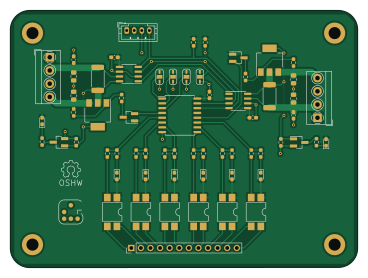
About the Pcb pox
Pcb pox is an open source PCB design by geertu, published on GitHub. It is a 2-layer board measuring 91.9 × 68 mm, with 64 components from 20 distinct parts.
Other key parts include the PCF8574, INA219xID and HCPL-181. By type, the board carries 24 resistors, 9 ICs, 9 capacitors, 8 diodes, 6 transistors and 4 connectors.
From the project
Power-Opto Extension (PCB)
This is a small extension board to control operation of two development boards, e.g. on your desk, or in a board farm. It is mainly intended for use with BCU/2 (https://github.com/geertu/pcb-bcu2), but it can be used with any microcontroller or single-board computer that has a compatible I2C interface.
- Controlled over I2C, - Two power control and measurement channels (3.3-14V, max. 3.2A), - Six opto-isolators for e.g. reset, wake-up, and keypress simulation.
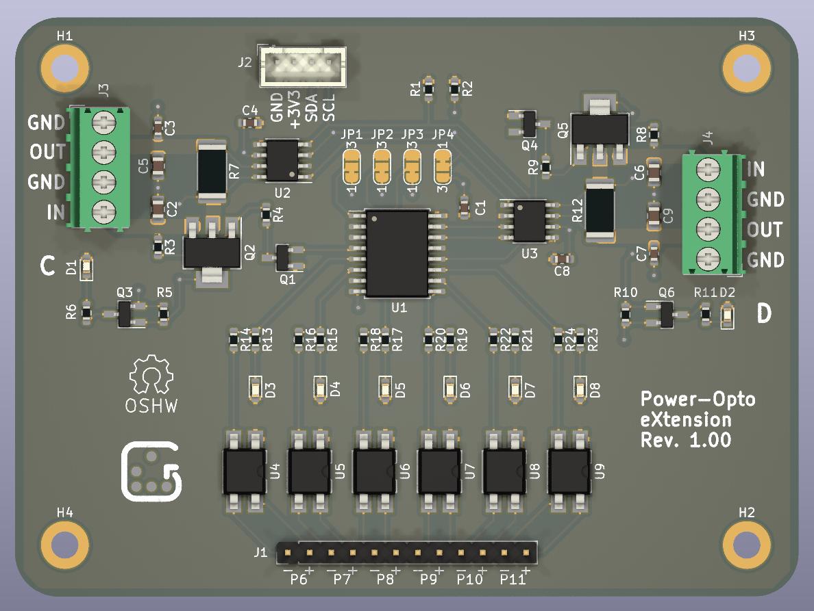
Main components on the Pcb pox
Pcb pox bill of materials (BOM)
64 components, 20 distinct parts.
| Qty | Part | Footprint | Refs |
|---|---|---|---|
| 1 | PCF8574 | SOIC-16W_7.5x10.3mm_P1.27mm | U1 |
| 2 | INA219xID | SOIC-8_3.9x4.9mm_P1.27mm | U2, U3 |
| 6 | HCPL-181 | SMDIP-4_W7.62mm | U4, U5, U6, U7, U8, U9 |
| 4 | 2N7002 | SOT-23_Handsoldering | Q1, Q3, Q4, Q6 |
| 2 | DMP6023LE-13 | SOT-223-3_TabPin2 | Q2, Q5 |
| 1 | Conn_01x12_Male | PinHeader_1x12_P2.54mm_Vertical | J1 |
| 1 | Conn_01x04_Male | JST_PH_B4B-PH-K_1x04_P2.00mm_Vertical | J2 |
| 2 | Screw_Terminal_01x04 | TerminalBlock_MetzConnect_Type059_RT06304HBWC_1x04_P3.50mm_Horizontal | J3, J4 |
| 4 | SolderJumper_3_Bridged12 | SolderJumper-3_P1.3mm_Bridged12_RoundedPad1.0x1.5mm_NumberLabels | JP1, JP2, JP3, JP4 |
| 2 | Green | LED_0603_1608Metric_Pad1.05x0.95mm_HandSolder | D1, D2 |
| 6 | Yellow | LED_0603_1608Metric_Pad1.05x0.95mm_HandSolder | D3, D4, D5, D6, D7, D8 |
| 5 | 100n | C_0603_1608Metric_Pad1.08x0.95mm_HandSolder | C1, C3, C4, C7, C8 |
| 4 | 10µ | C_0805_2012Metric_Pad1.18x1.45mm_HandSolder | C2, C5, C6, C9 |
| 2 | 4K7 | R_0603_1608Metric_Pad0.98x0.95mm_HandSolder | R1, R2 |
| 2 | 47K | R_0603_1608Metric_Pad0.98x0.95mm_HandSolder | R3, R8 |
| 2 | 10K | R_0603_1608Metric_Pad0.98x0.95mm_HandSolder | R4, R9 |
| 2 | 100K | R_0603_1608Metric_Pad0.98x0.95mm_HandSolder | R5, R10 |
| 8 | 1K | R_0603_1608Metric_Pad0.98x0.95mm_HandSolder | R6, R11, R13, R15, R17, R19, R21, R23 |
| 2 | 0.1 1% 2W | R_2512_6332Metric_Pad1.40x3.35mm_HandSolder | R7, R12 |
| 6 | 270 | R_0603_1608Metric_Pad0.98x0.95mm_HandSolder | R14, R16, R18, R20, R22, R24 |
Pcb pox design files
The KiCad project lives in the geertu/pcb-pox repository on GitHub; these links point at the commit this page was built from.
- LayoutBCU2-POX.kicad_pcb
- SchematicBCU2-POX.kicad_sch
Pcb pox: common questions
How big is the Pcb pox?
The Pcb pox measures 91.9 × 68 mm, has 2 copper layers and is 1.6 mm thick.
How many components are on the Pcb pox?
64 components, from 20 distinct parts. The full bill of materials is listed on this page.
Where can I download the Pcb pox design files?
From the geertu/pcb-pox repository on GitHub, which has the KiCad layout and the schematic; the links under Design files point to each one.
Can I use the Pcb pox design in my own project?
The repository has no license, so all rights stay with geertu. Use it as a reference, and ask the author before reusing the design.