
RTB C10

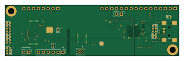
About the RTB C10 PCB
RTB C10 is an open source AVR/Arduino PCB design by git4dcc, published on GitHub under the Apache-2.0 license. It is a 2-layer board measuring 90.3 × 26.5 mm, with 79 components from 42 distinct parts.
Its main chip is the AVR64DA48, from the AVR/Arduino family. Other key parts include the TPS2553DRVT, C547123, MIC5205-3.3YM5, FT230XQ and ISO7742. By type, the board carries 23 resistors, 20 capacitors, 19 diodes, 6 ICs, 5 connectors and 3 jumpers.
From the project
Model Railway Layout Control Bus-Master
My homebrew RTB C10 Bus Master connects the PC with the model railway layout via USB. The bus master is responsible for the bus timing and scales from small testing beads to large scale layouts.
- RTBC11 - Power - RTBC12 - Booster - RTBC13 - Track Sensor - RTBP15 - Base
:yellowcircle: Requires my Kicad project library RTBSamacSys in the same directory tree.
This project is intended for hobby use only and is distributed in accordance with the Apache License 2.0 agreement.
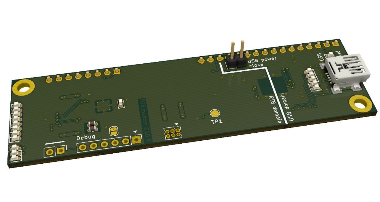
Main components on the RTB C10
RTB C10 bill of materials (BOM)
79 components, 42 distinct parts — part numbers from the project's BOM.
| Qty | Part | Footprint | Refs |
|---|---|---|---|
| 1 | TPS2553DRVT | SON65P200X200X80-7N | IC1 |
| 1 | C547123 74HC595BQ,115 | 74HC595BQ115 | IC3 |
| 1 | AVR64DA48 | UQFN-48-1EP_6x6mm_P0.4mm_EP4.45x4.45mm_ThermalVias | U2 |
| 1 | MIC5205-3.3YM5 | SOT-23-5 | U5 |
| 1 | FT230XQ | QFN-16-1EP_4x4mm_P0.65mm_EP2.7x2.7mm | U6 |
| 1 | ISO7742 | SSOP-16_3.9x4.9mm_P0.635mm | U7 |
| 1 | ASE-24MHZ ASE-24MHz | Oscillator_SMD_Abracon_ASE-4Pin_3.2x2.5mm | X1 |
| 1 | USB_B_Mini | USB_Micro-B_Reichelt_BWM_SMD | J1 |
| 1 | CONN_01X16_MALE Conn_01x16_Male | PinHeader_1x16_P2.54mm_Vertical | J2 |
| 1 | Debug IF | PinHeader_1x06_P2.54mm_Vertical | J3 |
| 1 | UPDI | PinHeader_2x03_P1.27mm_Vertical | J4 |
| 1 | CONN_01X08_MALE Conn_01x08_Male | PinHeader_1x08_P2.54mm_Vertical | J5 |
| 1 | SOLDERJUMPER_2_OPEN SolderJumper_2_Open | SolderJumper-2_P1.3mm_Open_RoundedPad1.0x1.5mm | JP1 |
| 1 | JUMPER_2_OPEN Jumper_2_Open | PinHeader_1x02_P2.54mm_Vertical | JP2 |
| 1 | USB power | PinHeader_1x02_P2.54mm_Vertical | JP3 |
| 1 | C130413 BAS16H,115 | D_SOD-123F | D1 |
| 1 | C434421 Locate(blue) | LED_0603_1608Metric | D2 |
| 1 | C2986060 Reset(red) | LED_0603_1608Metric | D3 |
| 1 | C84264 Hbt(grn) | LED_0603_1608Metric | D4 |
| 1 | C84264 PWR(grn) | LED_0603_1608Metric | D5 |
Show 22 more
| Qty | Part | Footprint | Refs |
|---|---|---|---|
| 1 | Alarm(pink) | LED_0603_1608Metric | D6 |
| 1 | PWR(grn) | LED_0603_1608Metric | D8 |
| 2 | LED(grn) | LED_0603_1608Metric | D11, D12 |
| 8 | C2290 LED(wht) | LED_0603_1608Metric | D14, D32, D33, D34, D35, D36, D37, D38 |
| 1 | RTS(red) | LED_0603_1608Metric | D17 |
| 1 | CTS(red) | LED_0603_1608Metric | D18 |
| 2 | C845118 Ferrite_Bead | L_0805_2012Metric | L1, L2 |
| 1 | 100NF/50V 100nF/50V | C_0805_2012Metric | C2 |
| 1 | 10UF/25V 10uF/25V | C_0805_2012Metric | C3 |
| 12 | 100NF 100nF | C_0603_1608Metric | C4, C5, C7, C8, C9, C10, C11, C12 +4 |
| 1 | 4.7UF 4.7uF | R_0603_1608Metric | C6 |
| 2 | 47PF 47pF | C_0603_1608Metric | C14, C15 |
| 1 | 22UF/25V 22uF/25V | C_1206_3216Metric | C16 |
| 2 | 220U/6.3V 220u/6.3V | C_1206_3216Metric | C19, C20 |
| 5 | 1k | R_0603_1608Metric | R1, R6, R7, R8, R12 |
| 10 | 3.3K 3.3k | R_0603_1608Metric | R2, R4, R5, R11, R15, R22, R23, R28 +2 |
| 1 | 100 | R_0603_1608Metric | R3 |
| 1 | 100K 100k | R_0603_1608Metric | R9 |
| 1 | 18K 22k | R_0603_1608Metric | R10 |
| 2 | 27 | R_0603_1608Metric | R16, R20 |
| 1 | 0 | R_0603_1608Metric | R27 |
| 2 | 4.7K 4.7k | R_Array_Convex_4x0603 | RN3, RN4 |
RTB C10 design files
The KiCad project lives in the git4dcc/RTB_C10 repository on GitHub; these links point at the commit this page was built from.
- LayoutC10.kicad_pcb
- SchematicC10.kicad_sch
- BOMgerber/C10_4_BOM.csv
RTB C10: common questions
What microcontroller does the RTB C10 use?
The RTB C10 is built around the AVR64DA48, from the AVR/Arduino family.
How big is the RTB C10 PCB?
The RTB C10 measures 90.3 × 26.5 mm, has 2 copper layers and is 1.6 mm thick.
How many components are on the RTB C10?
79 components, from 42 distinct parts, with part numbers taken from the project's own BOM. The full bill of materials is listed on this page.
Where can I download the RTB C10 design files?
From the git4dcc/RTB_C10 repository on GitHub, which has the KiCad layout, the schematic and the BOM; the links under Design files point to each one.
Can I use the RTB C10 design in my own project?
Yes, under the terms of its Apache-2.0 license, which git4dcc chose for the repository.
Can I test firmware for the RTB C10 without the hardware?
Yes. HardLabs builds a simulation of the board from its netlist and BOM, so you can run and debug AVR/Arduino firmware against it before you order a PCB.
Similar boards
 AVR/Arduino
Magspoof
samyk
35 × 29 mm11 parts2LNo license4.2k AVR/Arduino
Redox keyboard
mattdibi
162.2 × 126.5 mm77 parts2LMIT2.0k AVR/Arduino
Labrador
espotek-org
36.8 × 34.7 mm75 parts2LNo license1.2k AVR/Arduino
V4
stuartpittaway
30 × 50 mm38 parts2LCC-BY-NC-4.01.1k AVR/Arduino
ModuleV450
30 × 61.4 mm39 parts2LCC-BY-NC-4.01.1k AVR/Arduino
Discipline
coseyfannitutti
304.9 × 122.8 mm170 parts2LCC-BY-NC-4.01.0k