
RTB E10

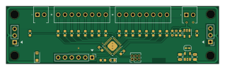
About the RTB E10 PCB
RTB E10 is an open source PCB design by git4dcc, published on GitHub under the Apache-2.0 license. It is a 2-layer board measuring 79.4 × 21.6 mm, with 39 components from 19 distinct parts.
Other key parts include the C3225675, C7473162 and C116490. By type, the board carries 22 resistors, 8 connectors, 4 capacitors, 3 ICs and 2 diodes.
It belongs with the displays & leds designs in this gallery.
From the project
Universal 16 channel WS28xx emulator.
This E10 module implements a 16 channel WS2811 emulator with compatible bus timing. The E10 may be cascaded with regular WS28xx chips. The number of LEDs is auto detected/configured (0-16). Optionally, the common LED voltage can be controlled over the bus as well.
The decoder has the following features, - Protocol - WS2811 compatible timing - LED ports - 0..16 channel output (auto detecting) - Software selectable common LED voltage (0 .. 5V) - Push/Pull output and can drive common anode or cathode - 256 step PWM (240Hz) - gamma correction (optional) - firmware update via V24 debug interface
Main components on the RTB E10
RTB E10 bill of materials (BOM)
39 components, 19 distinct parts — part numbers from the project's BOM.
| Qty | Part | Footprint | Refs |
|---|---|---|---|
| 1 | C3225675 AVR-64da32 | QFN-32-1EP_5x5mm_P0.5mm_EP3.1x3.1mm | U1 |
| 1 | C7473162 MIC5205-5.0YM5 | SOT-23-5 | U2 |
| 1 | C116490 MCP6001 | SOT-23-5 | U3 |
| 1 | LED 8-15 | 1725711 | J1 |
| 1 | WS-bus output | PinHeader_1x03_P2.54mm_Vertical | J2 |
| 1 | WS-bus input | PinHeader_1x03_P2.54mm_Vertical | J3 |
| 1 | UPDI | PinHeader_2x03_P1.27mm_Vertical | J4 |
| 1 | Debug | PinHeader_1x06_P2.54mm_Vertical | J5 |
| 2 | LED Common | 1725656 | J6, J8 |
| 1 | LED 0-7 | 1725711 | J7 |
| 1 | C719833 SS34F | D_SOD-123F | D1 |
| 1 | C84264 HBT(green) | LED_0603_1608Metric | D2 |
| 2 | C1779 4.7u/10V | C_0805_2012Metric | C1, C4 |
| 2 | C14663 100n | C_0603_1608Metric | C2, C3 |
| 16 | C22962 220 | R_0603_1608Metric | R2, R3, R4, R5, R6, R7, R8, R9 +8 |
| 2 | C22808 160 | R_0603_1608Metric | R18, R19 |
| 1 | C23162 4.7k | R_0603_1608Metric | R20 |
| 1 | C23345 22 | R_0603_1608Metric | R23 |
| 2 | C25819 47k | R_0603_1608Metric | R24, R25 |
RTB E10 design files
The KiCad project lives in the git4dcc/RTB_E10 repository on GitHub; these links point at the commit this page was built from.
- LayoutE10.kicad_pcb
- BOMgerber/E10_3-bom.csv
RTB E10: common questions
How big is the RTB E10 PCB?
The RTB E10 measures 79.4 × 21.6 mm, has 2 copper layers and is 1.6 mm thick.
How many components are on the RTB E10?
39 components, from 19 distinct parts, with part numbers taken from the project's own BOM. The full bill of materials is listed on this page.
Where can I download the RTB E10 design files?
From the git4dcc/RTB_E10 repository on GitHub, which has the KiCad layout and the BOM; the links under Design files point to each one.
Can I use the RTB E10 design in my own project?
Yes, under the terms of its Apache-2.0 license, which git4dcc chose for the repository.
Similar boards
BM28B0.6-24DSBreakout
scottbez1
15.2 × 35.6 mm3 parts2LApache-2.022.2k
LevelShifterBreakout
15.2 × 20.3 mm5 parts2LApache-2.022.2k
View base
81.2 × 81.2 mm81 parts2LApache-2.022.2k
View screen
35 × 35 mm12 parts2LApache-2.022.2k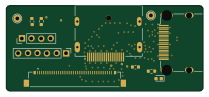
Display eval
byrantech
52.1 × 22.6 mm12 parts4LMIT4.3k
ChainlinkBase
98.4 × 190.5 mm119 parts2LApache-2.04.2k