Separator

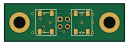
About the Separator PCB
Separator is an open source PCB design by GraniteGobbler, published on GitHub. It is a 2-layer board measuring 32 × 10 mm, with 8 components from 5 distinct parts.
By type, the board carries 2 diodes, 2 capacitors, 2 resistors, 1 transistor and 1 connector.
From the project
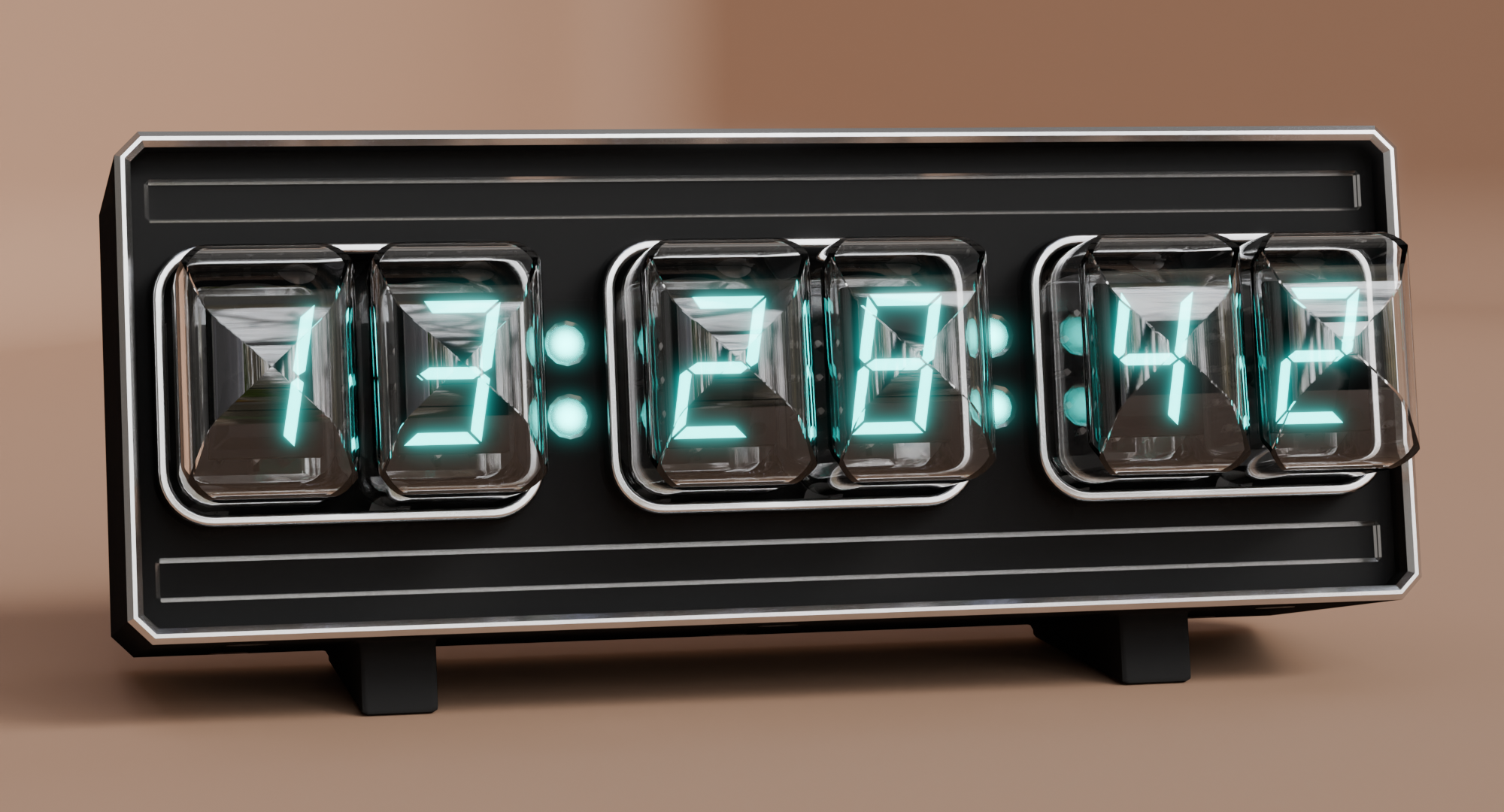
ESP32-S3 -based IV-22 desk clock
Separator bill of materials (BOM)
8 components, 5 distinct parts — part numbers from the project's BOM.
| Qty | Part | Footprint | Refs |
|---|---|---|---|
| 1 | BSS138 | SOT-23 | Q1 |
| 1 | COL_CONN | PinHeader_2x02_P2.00mm_Vertical | J1 |
| 2 | INOLUX_IN-PI554FCH Inolux_IN-PI554FCH | LED_Inolux_IN-PI554FCH_PLCC4_5.0x5.0mm_P3.2mm | D1, D2 |
| 2 | 100N 100n | C_0805_2012Metric | C1, C2 |
| 2 | 10K 10k | R_0805_2012Metric | R1, R2 |
Separator design files
The KiCad project lives in the GraniteGobbler/VFDClock repository on GitHub; these links point at the commit this page was built from.
Separator: common questions
How big is the Separator PCB?
The Separator measures 32 × 10 mm, has 2 copper layers and is 1.6 mm thick.
How many components are on the Separator?
8 components, from 5 distinct parts, with part numbers taken from the project's own BOM. The full bill of materials is listed on this page.
Where can I download the Separator design files?
From the GraniteGobbler/VFDClock repository on GitHub, which has the KiCad layout, the schematic and the BOM; the links under Design files point to each one.
Can I use the Separator design in my own project?
The repository has no license, so all rights stay with GraniteGobbler. Use it as a reference, and ask the author before reusing the design.