Rx


About the Rx PCB
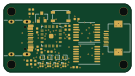
Rx is an open source PCB design by gregdavill, published on GitHub. It is a 2-layer board measuring 150 × 8 mm, with 9 components from 2 distinct parts.
By type, the board carries 8 test points and 1 connector.
From the project
A prototype of a flex measuring sensor. Based off: https://dl.acm.org/doi/10.1145/3313831.3376269
A prototype of a flex measuring sensor. Based off: https://dl.acm.org/doi/10.1145/3313831.3376269
This design will attempt to utilise OSHPark Flex for the sensor elements, which provides a low cost solution for prototyping flexible circuits. But you are limited to a 5mil polymide core.
Rx bill of materials (BOM)
9 components, 2 distinct parts.
| Qty | Part | Footprint | Refs |
|---|---|---|---|
| 1 | Conn_01x08_Male | 8P_0.5mm_FFC | J1 |
| 8 | CapSense | CapSense | TP1, TP2, TP3, TP4, TP5, TP6, TP7, TP8 |
Rx design files
The KiCad project lives in the gregdavill/cap-sense-flex repository on GitHub; these links point at the commit this page was built from.
- Layouthardware/Rx-r0.1/Rx.kicad_pcb
- Schematichardware/Rx-r0.1/Rx.kicad_sch
Rx: common questions
How big is the Rx PCB?
The Rx measures 150 × 8 mm, has 2 copper layers and is 0.2478 mm thick.
How many components are on the Rx?
9 components, from 2 distinct parts. The full bill of materials is listed on this page.
Where can I download the Rx design files?
From the gregdavill/cap-sense-flex repository on GitHub, which has the KiCad layout and the schematic; the links under Design files point to each one.
Can I use the Rx design in my own project?
The repository has no license, so all rights stay with gregdavill. Use it as a reference, and ask the author before reusing the design.