
Esphome sensor

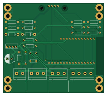
About the Esphome sensor PCB
Esphome sensor is an open source PCB design by gregrob, published on GitHub under the MIT license. It is a 2-layer board measuring 85 × 76 mm, with 26 components from 17 distinct parts.
Other key parts include the D24V5F5 and FEATHERS3D. By type, the board carries 13 resistors, 5 connectors, 3 diodes, 3 capacitors and 2 ICs.
It belongs with the iot & wireless, sensors and displays & leds designs in this gallery.
From the project
esphome-sensor
An ESP32-S3 based sensor board system for ESPHome and Home Assistant, designed for outdoor environmental monitoring with a focus on hot water system and water tank level monitoring. Includes a complete mechanical system with 3D printable parts and a purpose-built outdoor 12V DC power distribution unit.
- ESP32-S3 (FeatherS3D) with WiFi and ESPHome integration - PiicoDev OLED display for local status indication - Dual 1-Wire buses for DS18B20 temperature sensors - I2C expansion for ToF distance sensors (DFRobot SEN0590) - RGB LED status indicator with gradient colour coding - Outdoor-rated…
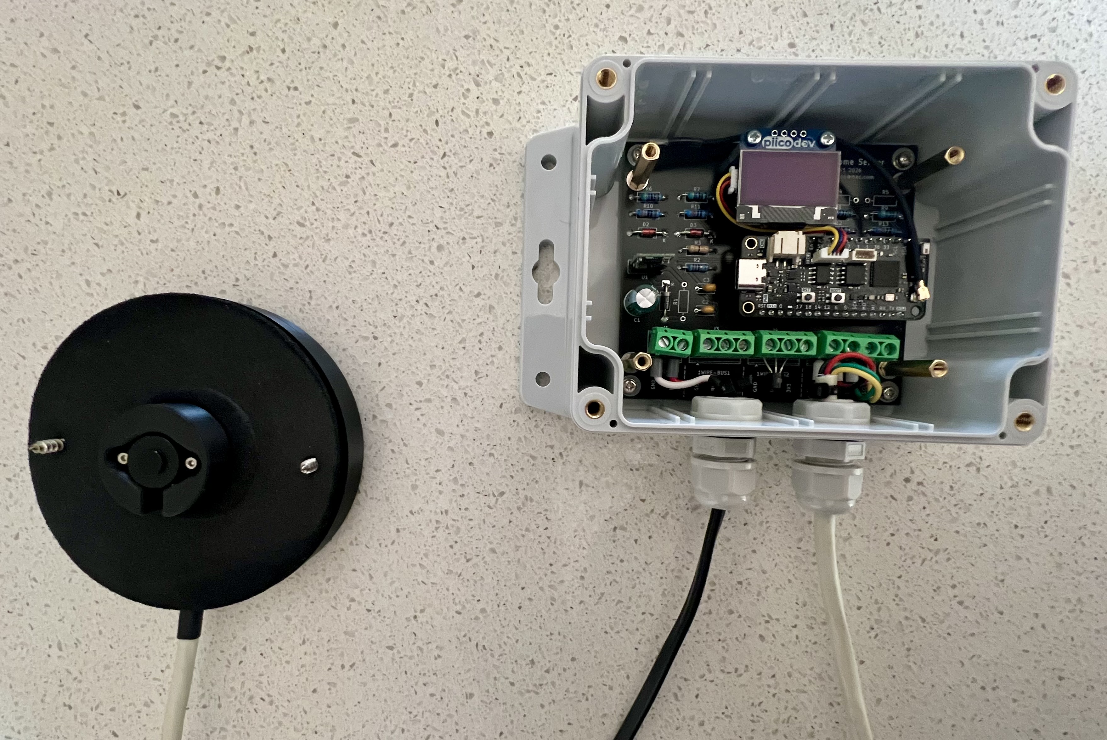
Main components on the Esphome sensor
Esphome sensor bill of materials (BOM)
26 components, 17 distinct parts — part numbers from the project's BOM.
| Qty | Part | Footprint | Refs |
|---|---|---|---|
| 1 | D24V5F5 | D24V5F5 | U1 |
| 1 | FEATHERS3D FeatherS3D | FeatherS3D | U2 |
| 1 | DC POWER IN | TerminalBlock_Phoenix_PT-1,5-2-5.0-H_1x02_P5.00mm_Horizontal | J1 |
| 1 | OLED | PiicoDev_OLED_Module | J2 |
| 1 | 1WIRE-BUS1 | TerminalBlock_Phoenix_PT-1,5-3-5.0-H_1x03_P5.00mm_Horizontal | J3 |
| 1 | 1WIRE-BUS2 | TerminalBlock_Phoenix_PT-1,5-3-5.0-H_1x03_P5.00mm_Horizontal | J4 |
| 1 | I2C | TerminalBlock_Phoenix_PT-1,5-4-5.0-H_1x04_P5.00mm_Horizontal | J5 |
| 1 | 1N4007 | D_DO-41_SOD81_P10.16mm_Horizontal | D1 |
| 2 | 1N4729A* | D_DO-41_SOD81_P10.16mm_Horizontal | D2, D3 |
| 1 | C_Polarized | CP_Radial_D8.0mm_P3.50mm | C1 |
| 2 | 100nF 50V | C_Disc_D5.0mm_W2.5mm_P5.00mm | C2, C3 |
| 1 | 0R* | R_Axial_DIN0207_L6.3mm_D2.5mm_P10.16mm_Horizontal | R1 |
| 1 | 22R | R_Axial_DIN0207_L6.3mm_D2.5mm_P10.16mm_Horizontal | R2 |
| 1 | 0R | R_Axial_DIN0207_L6.3mm_D2.5mm_P10.16mm_Horizontal | R3 |
| 2 | 4.7K* | R_Axial_DIN0207_L6.3mm_D2.5mm_P10.16mm_Horizontal | R4, R5 |
| 4 | 4.7K | R_Axial_DIN0207_L6.3mm_D2.5mm_P10.16mm_Horizontal | R6, R7, R8, R9 |
| 4 | 330R | R_Axial_DIN0207_L6.3mm_D2.5mm_P10.16mm_Horizontal | R10, R11, R12, R13 |
Esphome sensor design files
The KiCad project lives in the gregrob/esphome-sensor repository on GitHub; these links point at the commit this page was built from.
Esphome sensor: common questions
How big is the Esphome sensor PCB?
The Esphome sensor measures 85 × 76 mm, has 2 copper layers and is 1.6 mm thick.
How many components are on the Esphome sensor?
26 components, from 17 distinct parts, with part numbers taken from the project's own BOM. The full bill of materials is listed on this page.
Where can I download the Esphome sensor design files?
From the gregrob/esphome-sensor repository on GitHub, which has the KiCad layout, the schematic and the BOM; the links under Design files point to each one.
Can I use the Esphome sensor design in my own project?
Yes, under the terms of its MIT license, which gregrob chose for the repository.
Similar boards
BM28B0.6-24DSBreakout
scottbez1
15.2 × 35.6 mm3 parts2LApache-2.022.2k
LevelShifterBreakout
15.2 × 20.3 mm5 parts2LApache-2.022.2k
View base
81.2 × 81.2 mm81 parts2LApache-2.022.2k
View screen
35 × 35 mm12 parts2LApache-2.022.2k
Display eval
byrantech
52.1 × 22.6 mm12 parts4LMIT4.3k
ChainlinkBase
98.4 × 190.5 mm119 parts2LApache-2.04.2k