
SensorBoard

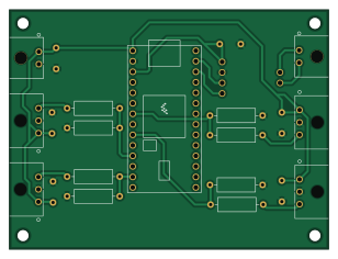
About the SensorBoard PCB
SensorBoard is an open source NXP PCB design by higg22-git, published on GitHub. It is a 2-layer board measuring 77 × 57.8 mm, with 22 components from 9 distinct parts.
Its main chip is the *, from the NXP family. By type, the board carries 8 resistors, 6 connectors, 6 capacitors and 1 IC.
It belongs with the sensors and rf & radio designs in this gallery.
From the project
CAN sensor node for BYU Formula SAE Electric. Teensy 4.0 with an SN65HVD230 transceiver and connectorized sensor inputs. KiCad schematic and layout.
CAN sensor node for BYU Formula SAE Electric's car. Reads analog and digital sensors and publishes them onto the vehicle CAN bus, so the ECU sees sensor data as CAN frames instead of a bundle of wires run back to a single board.
- Teensy 4.0 as the controller - SN65HVD230 CAN transceiver - Connectorized sensor inputs on Molex 2- and 3-pin headers, so a sensor can be swapped in the paddock without touching the board - Two-layer KiCad layout
Main components on the SensorBoard
SensorBoard bill of materials (BOM)
22 components, 9 distinct parts.
| Qty | Part | Footprint | Refs |
|---|---|---|---|
| 1 | * | Teensy40 | U1 |
| 4 | 3pinconnector | CONN_SD-43650-001_03_MOL(3pinconnector) | J1, J2, J3, J4 |
| 1 | 436500201 POWER | CONN_SD-43650-001_02_MOL(2pinconnector) | J5 |
| 1 | 436500201 2pinconnector(micro) | CONN_SD-43650-001_02_MOL(2pinconnector) | J6 |
| 1 | SN65HVD230 | CAN_FOOTPRINT | CAN1 |
| 5 | 100nF | 5.08 Capacitor | C1, C2, C3, C4, C5 |
| 1 | 10uF | 5.08 Capacitor | C6 |
| 4 | 1kΩ | R_Axial_DIN0309_L9.0mm_D3.2mm_P12.70mm_Horizontal | R1, R3, R5, R7 |
| 4 | 2kΩ | R_Axial_DIN0309_L9.0mm_D3.2mm_P12.70mm_Horizontal | R2, R4, R6, R8 |
SensorBoard design files
The KiCad project lives in the higg22-git/SensorBoard repository on GitHub; these links point at the commit this page was built from.
- LayoutSensorBoard.kicad_pcb
- SchematicSensorBoard.kicad_sch
SensorBoard: common questions
What microcontroller does the SensorBoard use?
The SensorBoard is built around the *, from the NXP family.
How big is the SensorBoard PCB?
The SensorBoard measures 77 × 57.8 mm, has 2 copper layers and is 1.6 mm thick.
How many components are on the SensorBoard?
22 components, from 9 distinct parts. The full bill of materials is listed on this page.
Where can I download the SensorBoard design files?
From the higg22-git/SensorBoard repository on GitHub, which has the KiCad layout and the schematic; the links under Design files point to each one.
Can I use the SensorBoard design in my own project?
The repository has no license, so all rights stay with higg22-git. Use it as a reference, and ask the author before reusing the design.
Can I test firmware for the SensorBoard without the hardware?
Yes. HardLabs builds a simulation of the board from its netlist and BOM, so you can run and debug NXP firmware against it before you order a PCB.
Similar boards
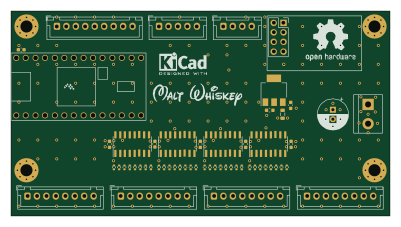 NXP
32Bit shift register
MaltWhiskey
100 × 54 mm56 parts4LNo license763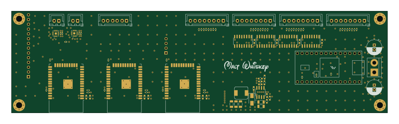 NXP
Mega-Cube-Board
200 × 54 mm100 parts4LNo license763 NXP
MCL6809
MicroCoreLabs
32.3 × 61 mm7 parts4LNo license532 NXP
MCL68
31.6 × 84.1 mm13 parts4LNo license532 NXP
MCL65+
72.6 × 64.1 mm6 parts2LNo license532 NXP
MCLZ8
37.1 × 61.5 mm6 parts4LNo license532