
Impedance tester

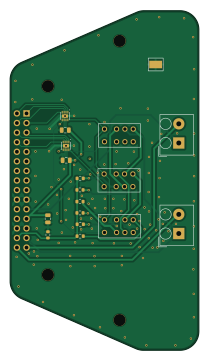
About the Impedance tester PCB
Impedance tester is an open source PCB design by hnz1102, published on GitHub. It is a 2-layer board measuring 50 × 90 mm, with 18 components from 13 distinct parts.
Other key parts include the A3910EEETR-T and AGN2104H. By type, the board carries 7 resistors, 5 ICs, 3 connectors and 3 capacitors.
It belongs with the test & measurement designs in this gallery.
From the project
Impedance Tester Adapter for Analog Discovery
A KiCad hardware design for a 4-terminal (Kelvin) impedance measurement adapter for the Digilent Analog Discovery / Analog Discovery 2 family of USB oscilloscope-and-instrument devices.
The Analog Discovery provides an arbitrary waveform generator and differential scope inputs, but no dedicated front end for accurate impedance measurement. This adapter plugs into the Analog Discovery's 2x15 pin header and adds the analog switching and signal conditioning needed to drive a device under test (DUT) and measure its impedance using a true 4-wire (Kelvin) connection, which removes the effect of…
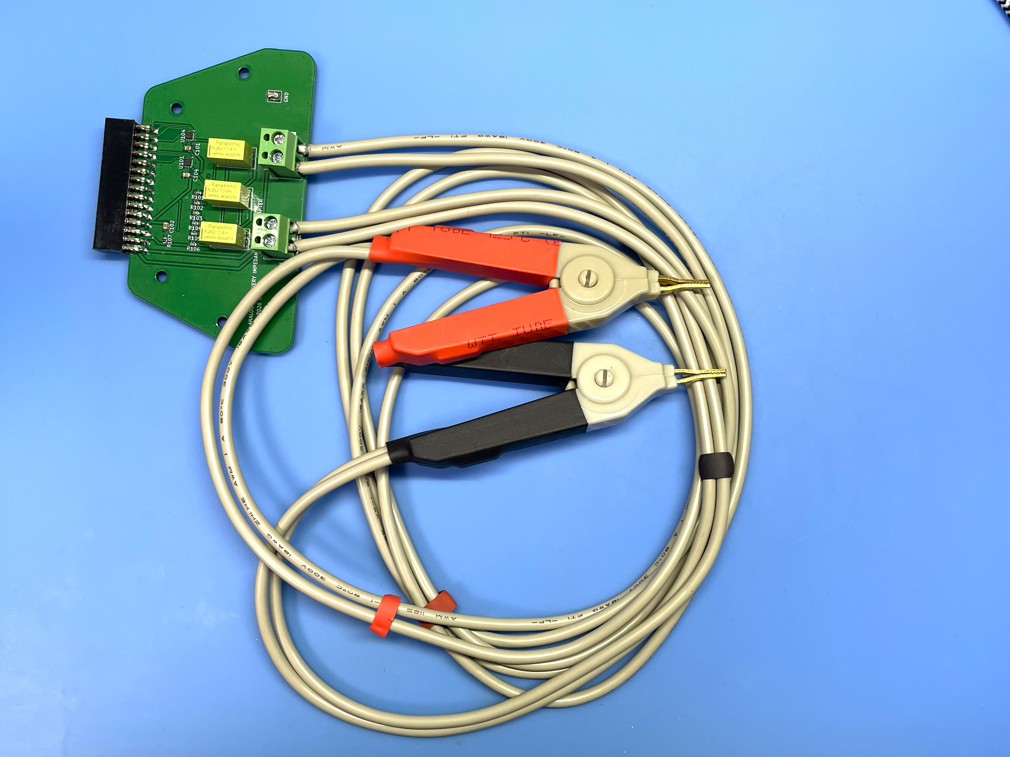
Main components on the Impedance tester
Impedance tester bill of materials (BOM)
18 components, 13 distinct parts — part numbers from the project's BOM.
| Qty | Part | Footprint | Refs |
|---|---|---|---|
| 2 | A3910EEETR-T | DFN-8-1EP_2x2mm_P0.5mm_EP0.9x1.6mm_W_TH | U101, U104 |
| 3 | AGN2104H | RELAY_AGN2104H | U102, U103, U108 |
| 2 | Screw_Terminal_01x02 | TB112-2-2-2-E-1 Terminal Block | J1, J2 |
| 1 | 02x15 2.54mmP F | PinHeader_2x15_P2.54mm_Vertical | J101 |
| 2 | 1uF | C_0805_2012Metric | C101, C104 |
| 1 | 10uF | C_0805_2012Metric | C102 |
| 1 | 10 1% | R_0603_1608Metric | R101 |
| 1 | 100 1% | R_0603_1608Metric | R102 |
| 1 | 1K 1% | R_0603_1608Metric | R103 |
| 1 | 10K 1% | R_0603_1608Metric | R104 |
| 1 | 100K 1% | R_0603_1608Metric | R105 |
| 1 | 1M 1% | R_0603_1608Metric | R106 |
| 1 | 0R | R_0603_1608Metric | R107 |
Impedance tester design files
The KiCad project lives in the hnz1102/impedance-tester repository on GitHub; these links point at the commit this page was built from.
Impedance tester: common questions
How big is the Impedance tester PCB?
The Impedance tester measures 50 × 90 mm, has 2 copper layers and is 1.6 mm thick.
How many components are on the Impedance tester?
18 components, from 13 distinct parts, with part numbers taken from the project's own BOM. The full bill of materials is listed on this page.
Where can I download the Impedance tester design files?
From the hnz1102/impedance-tester repository on GitHub, which has the KiCad layout, the schematic and the BOM; the links under Design files point to each one.
Can I use the Impedance tester design in my own project?
The repository has no license, so all rights stay with hnz1102. Use it as a reference, and ask the author before reusing the design.
Similar boards
DB9 High-Low Signal Generator
nanographs
47 × 30 mm10 parts2LNo license370
OneInchEye
will127534
39 × 39 mm79 parts4LMIT346
Integralstick mead
azonenberg
65 × 51.5 mm19 parts4LBSD-3-Clause193
Hmcad characterization
57 × 85 mm58 parts4LBSD-3-Clause193
Iob characterization v02
74.5 × 31 mm123 parts4LBSD-3-Clause193
Pmod prbs slow
41 × 20 mm43 parts4LBSD-3-Clause193