
HBD1E

About the HBD1E PCB
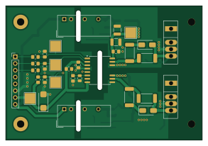
HBD1E is an open source PCB design by icosalogic, published on GitHub under the MIT license. It is a 2-layer board measuring 73.1 × 50 mm, with 48 components from 20 distinct parts.
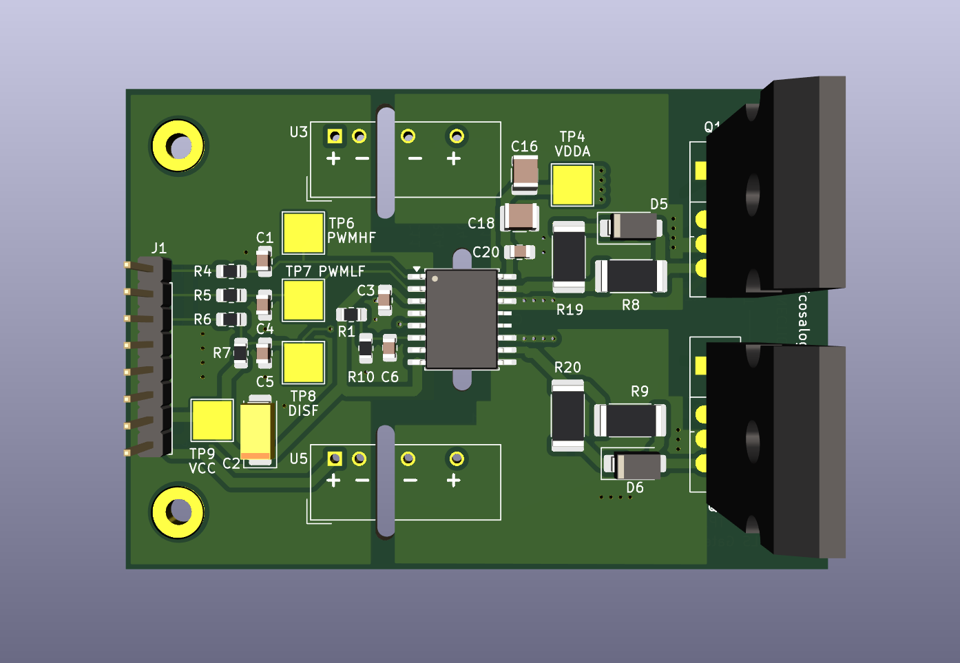
Other key parts include the UCC21520DW, LM317_SOT-223 and 3S7B-2424S3UP. By type, the board carries 18 resistors, 16 capacitors, 6 diodes, 5 ICs, 2 transistors and 1 connector.
From the project
Kicad project for a half bridge gate driver PCB for MOSFETs with TO-247-4 package and pinout [Drain,Source,KelvinSource,Gate].
- Supports 2 independent channels with 1 MOSFET per channel. - No high-power connections on the board. The user is free to connect the MOSFET power pins in any configuration they wish. - Utilizes a gate driver chip in an SOIC-16 wide package, with a pin layout supported by multiple vendors. - Each channel can be independently configured to be isolated from the gate driver control circuit. - Each channel can be independently configured to use a linear regulator to precisely control the gate driver voltage. - Most compatible gate driver chips support configurable dead time.
Main components on the HBD1E
HBD1E bill of materials (BOM)
48 components, 20 distinct parts — part numbers from the project's BOM.
| Qty | Part | Footprint | Refs |
|---|---|---|---|
| 1 | UCC21520DW | SOIC-16W_7.5x10.3mm_P1.27mm_no_pins_12_13 | U1 |
| 2 | LM317_SOT-223 | SOT-223-3_TabPin2 | U2, U4 |
| 2 | 3S7B-2424S3UP | Converter_DCDC_TRACO_TBA2-xxxx_Single_THT | U3, U5 |
| 2 | C3M0030090K | TO-247-4_Vertical | Q1, Q2 |
| 1 | Conn_01x08_Male | PinHeader_1x08_P2.54mm_Vertical | J1 |
| 4 | US1B | D_0805_2012Metric_Pad1.15x1.40mm_HandSolder | D1, D2, D3, D4 |
| 2 | US1B | D_SMA | D5, D6 |
| 2 | 33pF | C_0805_2012Metric_Pad1.18x1.45mm_HandSolder | C1, C4 |
| 1 | 2.2uF | CP_EIA-6032-20_AVX-F_Pad2.25x2.35mm_HandSolder | C2 |
| 7 | 0.1uF | C_0805_2012Metric_Pad1.18x1.45mm_HandSolder | C3, C7, C9, C10, C11, C19, C20 |
| 1 | 1nF | C_0805_2012Metric_Pad1.18x1.45mm_HandSolder | C5 |
| 1 | 2.2nF | C_0805_2012Metric | C6 |
| 4 | 4.7uF | C_1210_3225Metric | C8, C16, C17, C18 |
| 4 | 47 | R_0805_2012Metric_Pad1.20x1.40mm_HandSolder | R1, R4, R5, R6 |
| 3 | 10k | R_0805_2012Metric_Pad1.20x1.40mm_HandSolder | R7, R17, R18 |
| 4 | 2 | R_2512_6332Metric_Pad1.40x3.35mm_HandSolder | R8, R9, R19, R20 |
| 1 | 3.9k | R_0805_2012Metric_Pad1.20x1.40mm_HandSolder | R10 |
| 2 | 180 | R_0805_2012Metric_Pad1.20x1.40mm_HandSolder | R11, R16 |
| 2 | 1.2k | R_0805_2012Metric_Pad1.20x1.40mm_HandSolder | R12, R14 |
| 2 | 1.21k | R_0805_2012Metric_Pad1.20x1.40mm_HandSolder | R13, R15 |
HBD1E design files
The KiCad project lives in the icosalogic/HBD1E repository on GitHub; these links point at the commit this page was built from.
- LayoutHBD1E.kicad_pcb
- SchematicHBD1E.kicad_sch
- BOMHBD1E_BOM.csv
HBD1E: common questions
How big is the HBD1E PCB?
The HBD1E measures 73.1 × 50 mm, has 2 copper layers and is 1.6 mm thick.
How many components are on the HBD1E?
48 components, from 20 distinct parts, with part numbers taken from the project's own BOM. The full bill of materials is listed on this page.
Where can I download the HBD1E design files?
From the icosalogic/HBD1E repository on GitHub, which has the KiCad layout, the schematic and the BOM; the links under Design files point to each one.
Can I use the HBD1E design in my own project?
Yes, under the terms of its MIT license, which icosalogic chose for the repository.