
Plus Connector

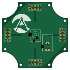
About the Plus Connector PCB
Plus Connector is an open source PCB design by irampton, published on GitHub under the MIT license. It is a 2-layer board measuring 60 × 60 mm, with 5 components from 2 distinct parts.
Plus Connector bill of materials (BOM)
5 components, 2 distinct parts — part numbers from the project's BOM.
| Qty | Part | Footprint | Refs |
|---|---|---|---|
| 1 | PJ-002BH | PJ_002BH | 15V-28V DC |
| 4 | PZ2.54-2X5P-H25 JXTCONN(聚兴泰) | PZ2_54_2X5P_H25 | H1, H2, H3, H4 |
Plus Connector design files
The KiCad project lives in the irampton/LED_PCBs_V2 repository on GitHub; these links point at the commit this page was built from.
Plus Connector: common questions
How big is the Plus Connector PCB?
The Plus Connector measures 60 × 60 mm, has 2 copper layers and is 1.6 mm thick.
How many components are on the Plus Connector?
5 components, from 2 distinct parts, with part numbers taken from the project's own BOM. The full bill of materials is listed on this page.
Where can I download the Plus Connector design files?
From the irampton/LED_PCBs_V2 repository on GitHub, which has the KiCad layout, the schematic and the BOM; the links under Design files point to each one.
Can I use the Plus Connector design in my own project?
Yes, under the terms of its MIT license, which irampton chose for the repository.
More boards in LED_PCBs_V2
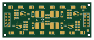
2x2x4-LED-Panel
75 × 30 mm56 parts2LMIT0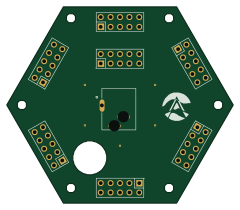
Hex Connector - Advanced
60 × 52 mm8 parts2LMIT0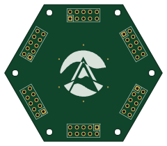
Hex Connector - Simple
60 × 52 mm6 parts2LMIT0
Square Connector
19 × 61 mm4 parts2LMIT0 ESP32
ESP32-Super-Mini-LED-Controller
53 × 30 mm4 parts2LMIT0
Right Angle Plug
30 × 30 mm3 parts2LMIT0