
USB-LED-Otter


About the USB-LED-Otter PCB
USB-LED-Otter is an open source STM32 PCB design by Jana-Marie, published on GitHub under the CERN-OHL-1.2 license. It is a 2-layer board measuring 12 × 15 mm, with 14 components from 8 distinct parts.
Its main chip is the STM32F072CBU6, from the STM32 family. Other key parts include the MCP1700T-3302E/TT. By type, the board carries 5 connectors, 5 capacitors, 2 ICs, 1 switch and 1 resistor.
It belongs with the usb & debug tools designs in this gallery.
From the project
Tiny USB to adressable LED adapter. Fits in your USB port :3
$ cd USB-LED-Otter-FW $ make $ dfu-util -a 0 -s 0x08000000:leave -D build/firmware.bin
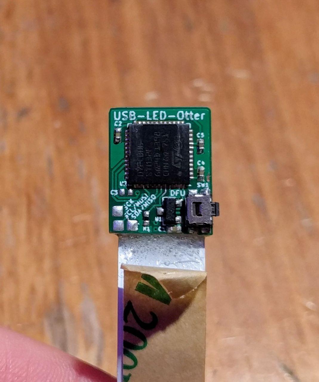
Main components on the USB-LED-Otter
USB-LED-Otter bill of materials (BOM)
14 components, 8 distinct parts — part numbers from the project's BOM.
| Qty | Part | Footprint | Refs |
|---|---|---|---|
| 1 | MCP1700T-3302E/TT MCP1700-3302E_SOT23 | SOT-23 | U1 |
| 1 | STM32F072CBU6 STM32F072CBUx | QFN-48-1EP_7x7mm_P0.5mm_EP2.6x2.6mm | U2 |
| 1 | USB | USBPCB | J1 |
| 3 | PAD | Pad_0.80.8 | J2, J4, J5 |
| 1 | LED | LED-Strip | J3 |
| 1 | EVQ-P7A01P DFU | SW_SPST_EVQP7A | SW1 |
| 5 | 100N 100n | C_0402_1005Metric | C1, C2, C3, C4, C5 |
| 1 | CRCW120610K0FKEA 10k Vishay | R_0402_1005Metric | R1 |
USB-LED-Otter design files
The KiCad project lives in the Jana-Marie/USB-LED-Otter repository on GitHub; these links point at the commit this page was built from.
- LayoutUSB-LED-Otter.kicad_pcb
- BOMBOM.csv
USB-LED-Otter: common questions
What microcontroller does the USB-LED-Otter use?
The USB-LED-Otter is built around the STM32F072CBU6, from the STM32 family.
How big is the USB-LED-Otter PCB?
The USB-LED-Otter measures 12 × 15 mm, has 2 copper layers and is 1.6 mm thick.
How many components are on the USB-LED-Otter?
14 components, from 8 distinct parts, with part numbers taken from the project's own BOM. The full bill of materials is listed on this page.
Where can I download the USB-LED-Otter design files?
From the Jana-Marie/USB-LED-Otter repository on GitHub, which has the KiCad layout and the BOM; the links under Design files point to each one.
Can I use the USB-LED-Otter design in my own project?
Yes, under the terms of its CERN-OHL-1.2 license, which Jana-Marie chose for the repository.
Can I test firmware for the USB-LED-Otter without the hardware?
Yes. HardLabs builds a simulation of the board from its netlist and BOM, so you can run and debug STM32 firmware against it before you order a PCB.
Similar boards
 STM32
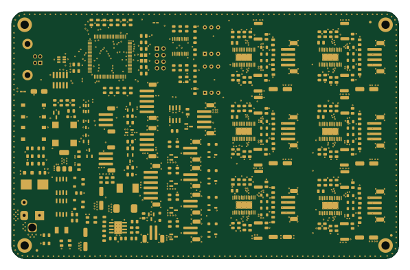
LumenPnP Motherboard
opulo-inc
149 × 95 mm296 parts4LCC-BY-SA-4.03.7k STM32
Base
google
52.3 × 52.3 mm36 parts2LApache-2.02.9k STM32
Type g
169 × 30 mm24 parts2LApache-2.02.9k STM32
Main panel
234 × 84 mm26 parts4LApache-2.02.9k STM32
Type a
150 × 30 mm14 parts2LApache-2.02.9k STM32
Type c
188 × 30 mm17 parts2LApache-2.02.9k