
Logic gate calculator

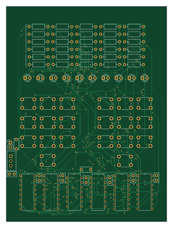
About the Logic gate calculator PCB
Logic gate calculator is an open source PCB design by jaydenaleung, published on GitHub. It is a 2-layer board measuring 86 × 115 mm, with 77 components from 31 distinct parts.
Other key parts include the N14, N16 and L7805. By type, the board carries 30 resistors, 20 switches, 10 diodes, 9 capacitors, 7 ICs and 1 connector.
From the project
A basic calculator made entirely from scratch using logic gates.
A custom calculator on a printed circuit board (PCB), made entirely from logic gates. The calculator takes in any number of inputs from 0-9 and can output their sum (up to 9). -----
GitHub Link: https://github.com/jaydenaleung/logic-gate-calculator. Included: KiCad project file/gerbers, pictures of schematic and PCB layout/render, bill of materials, README, and .step CAD file.
Main components on the Logic gate calculator
Logic gate calculator bill of materials (BOM)
77 components, 31 distinct parts.
| Qty | Part | Footprint | Refs |
|---|---|---|---|
| 2 | N14 | SN74HC04N | U34, U39 |
| 1 | N16 | SN74HC42N | U35 |
| 2 | N16 | CD74HC147E | U36, U38 |
| 1 | N16 | CD74HC283E | U37 |
| 1 | L7805 | L7805CV | U40 |
| 1 | Power_Dupont_Socket_Connector | PinHeader_1x02_P2.54mm_Vertical | J1 |
| 1 | SW_0_in_A | SW_PUSH_6mm | SW21 |
| 1 | SW_1_in_A | SW_PUSH_6mm | SW22 |
| 1 | SW_2_in_A | SW_PUSH_6mm | SW23 |
| 1 | SW_3_in_A | SW_PUSH_6mm | SW24 |
| 1 | SW_4_in_A | SW_PUSH_6mm | SW25 |
| 1 | SW_5_in_A | SW_PUSH_6mm | SW26 |
| 1 | SW_6_in_A | SW_PUSH_6mm | SW27 |
| 1 | SW_7_in_A | SW_PUSH_6mm | SW28 |
| 1 | SW_8_in_A | SW_PUSH_6mm | SW29 |
| 1 | SW_9_in_A | SW_PUSH_6mm | SW30 |
| 1 | SW_0_in_B | SW_PUSH_6mm | SW31 |
| 1 | SW_1_in_B | SW_PUSH_6mm | SW32 |
| 1 | SW_2_in_B | SW_PUSH_6mm | SW33 |
| 1 | SW_3_in_B | SW_PUSH_6mm | SW34 |
Show 11 more
| Qty | Part | Footprint | Refs |
|---|---|---|---|
| 1 | SW_4_in_B | SW_PUSH_6mm | SW35 |
| 1 | SW_5_in_B | SW_PUSH_6mm | SW36 |
| 1 | SW_6_in_B | SW_PUSH_6mm | SW37 |
| 1 | SW_7_in_B | SW_PUSH_6mm | SW38 |
| 1 | SW_8_in_B | SW_PUSH_6mm | SW39 |
| 1 | SW_9_in_B | SW_PUSH_6mm | SW40 |
| 10 | LED | LED_D3.0mm | D58, D59, D60, D61, D62, D63, D64, D65 +2 |
| 2 | 2.2µF | C_Disc_D6.0mm_W2.5mm_P5.00mm | C1, C9 |
| 7 | 0.1µF | C_Disc_D5.0mm_W2.5mm_P2.50mm | C2, C3, C4, C5, C6, C7, C8 |
| 20 | 10kΩ | R_Axial_DIN0207_L6.3mm_D2.5mm_P10.16mm_Horizontal | R31, R32, R33, R34, R35, R36, R37, R38 +12 |
| 10 | 220Ω | R_Axial_DIN0207_L6.3mm_D2.5mm_P10.16mm_Horizontal | R51, R52, R53, R54, R55, R56, R57, R58 +2 |
Logic gate calculator design files
The KiCad project lives in the jaydenaleung/logic-gate-calculator repository on GitHub; these links point at the commit this page was built from.
Logic gate calculator: common questions
How big is the Logic gate calculator PCB?
The Logic gate calculator measures 86 × 115 mm, has 2 copper layers and is 1.6 mm thick.
How many components are on the Logic gate calculator?
77 components, from 31 distinct parts. The full bill of materials is listed on this page.
Where can I download the Logic gate calculator design files?
From the jaydenaleung/logic-gate-calculator repository on GitHub, which has the KiCad layout and the schematic; the links under Design files point to each one.
Can I use the Logic gate calculator design in my own project?
The repository has no license, so all rights stay with jaydenaleung. Use it as a reference, and ask the author before reusing the design.