Carrier

About the Carrier PCB
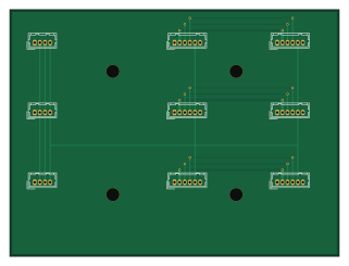
Carrier is an open source PCB design by Jettanakorn, published on GitHub. It is a 2-layer board measuring 80 × 60 mm, with 9 components from 9 distinct parts.
From the project
Hardware design for the 3-board TMR array. Firmware lives everywhere else in this repo; nothing here is compiled or linked into it.
Hardware design for the 3-board TMR array. Firmware lives everywhere else in this repo; nothing here is compiled or linked into it.
The only copy of the PX4FMUv2.4.5 schematic previously in this repo was docs/PX4FMUv2.4.5.pdf — a vector PDF with no extractable text. Every hardware fact taken from it had to be read off rendered page images by eye. That is fine for orientation and bad as a foundation for a new board design.
Carrier bill of materials (BOM)
9 components, 9 distinct parts.
| Qty | Part | Footprint | Refs |
|---|---|---|---|
| 1 | CAN A -> module J405 | Hirose_DF13-04P-1.25DSA_1x04_P1.25mm_Vertical | J1 |
| 1 | CAN B -> module J405 | Hirose_DF13-04P-1.25DSA_1x04_P1.25mm_Vertical | J2 |
| 1 | CAN C -> module J405 | Hirose_DF13-04P-1.25DSA_1x04_P1.25mm_Vertical | J3 |
| 1 | BRICK A in | Hirose_DF13-06P-1.25DSA_1x06_P1.25mm_Vertical | J4 |
| 1 | BRICK B in | Hirose_DF13-06P-1.25DSA_1x06_P1.25mm_Vertical | J5 |
| 1 | BRICK C in | Hirose_DF13-06P-1.25DSA_1x06_P1.25mm_Vertical | J6 |
| 1 | PWR A -> module J601 | Hirose_DF13-06P-1.25DSA_1x06_P1.25mm_Vertical | J7 |
| 1 | PWR B -> module J601 | Hirose_DF13-06P-1.25DSA_1x06_P1.25mm_Vertical | J8 |
| 1 | PWR C -> module J601 | Hirose_DF13-06P-1.25DSA_1x06_P1.25mm_Vertical | J9 |
Carrier design files
The KiCad project lives in the Jettanakorn/JFOX-FCU repository on GitHub; these links point at the commit this page was built from.
Carrier: common questions
How big is the Carrier PCB?
The Carrier measures 80 × 60 mm, has 2 copper layers and is 1.6 mm thick.
How many components are on the Carrier?
9 components, from 9 distinct parts. The full bill of materials is listed on this page.
Where can I download the Carrier design files?
From the Jettanakorn/JFOX-FCU repository on GitHub, which has the KiCad layout and the schematic; the links under Design files point to each one.
Can I use the Carrier design in my own project?
The repository has no license, so all rights stay with Jettanakorn. Use it as a reference, and ask the author before reusing the design.