
TVZSolderingPracticeKit

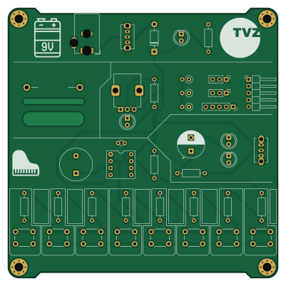
About the TVZSolderingPracticeKit PCB
TVZSolderingPracticeKit is an open source PCB design by jkordek1, published on GitHub. It is a 2-layer board measuring 100 × 100 mm, with 40 components from 28 distinct parts.
Other key parts include the NE555P. By type, the board carries 15 resistors, 10 switches, 5 connectors, 5 diodes, 2 capacitors and 1 IC.
From the project
This project is a custom-designed printed circuit board (PCB) developed as an educational tool to help students practice and develop through-hole device (THD) soldering skills. The board integrates simple but functional electronic circuits, centered around the NE555 timer IC, to
This project is a custom-designed printed circuit board (PCB) developed as an educational tool to help students practice and develop through-hole device (THD) soldering skills. The board integrates simple but functional electronic circuits, centered around the NE555 timer IC, to provide hands-on learning in both soldering and basic circuit operation.
Powered with 9V battery via barrel jack and adapter.
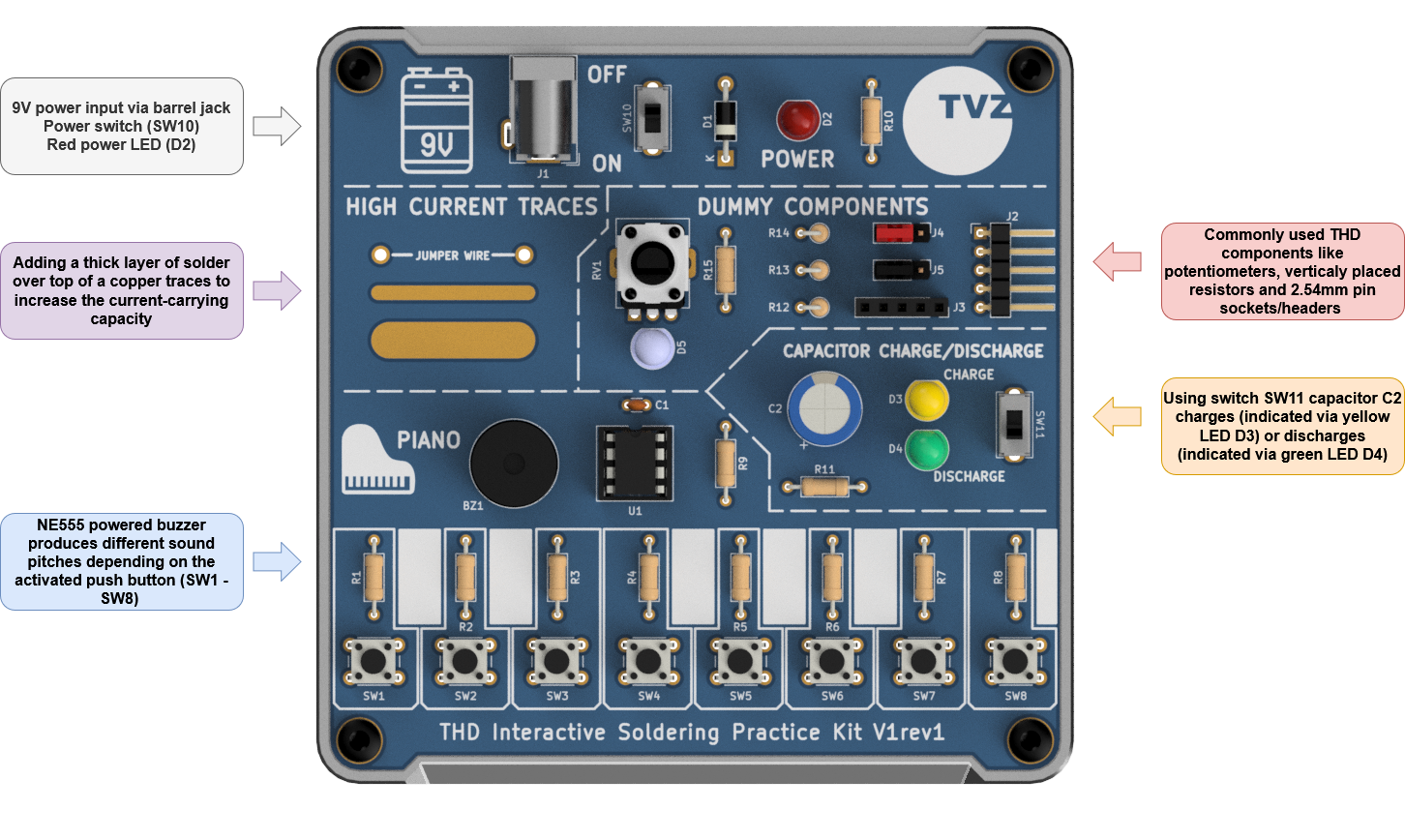
Main components on the TVZSolderingPracticeKit
TVZSolderingPracticeKit bill of materials (BOM)
40 components, 28 distinct parts — part numbers from the project's BOM.
| Qty | Part | Footprint | Refs |
|---|---|---|---|
| 1 | NE555P | DIP-8_W7.62mm-socket | U1 |
| 1 | Barrel Jack | DCJ250-10-A-K1-K | J1 |
| 1 | CONN_01X05_PIN Conn_01x05_Pin | PinHeader_1x05_P2.54mm_Horizontal | J2 |
| 1 | CONN_01X05_SOCKET Conn_01x05_Socket | PinSocket_1x05_P2.54mm_Vertical | J3 |
| 2 | CONN_01X03_PIN Conn_01x03_Pin | PinHeader_1x03_P2.54mm_Vertical | J4, J5 |
| 1 | LD-BZEN-1205 | LD-BZEN-1205 | BZ1 |
| 1 | 10K 10k | RK09K1130AH1 | RV1 |
| 8 | SW_Push | SW_PUSH_6mm_H4.3mm | SW1, SW2, SW3, SW4, SW5, SW6, SW7, SW8 |
| 1 | POWER | OS102011MS2QN1 | SW10 |
| 1 | C/D | OS102011MS2QN1 | SW11 |
| 1 | SR150-DC | D_DO-41_SOD81_P10.16mm_Horizontal | D1 |
| 1 | RED | LED_D5.0mm | D2 |
| 1 | YELLOW | LED_D5.0mm | D3 |
| 1 | GREEN | LED_D5.0mm | D4 |
| 1 | WHITE | LED_D5.0mm | D5 |
| 1 | 100N 100n | C_Disc_D3.0mm_W1.6mm_P2.50mm | C1 |
| 1 | 470u / 50V | CP_Radial_D10.0mm_P5.00mm | C2 |
| 1 | 1K5 1k5 | R_Axial_DIN0207_L6.3mm_D2.5mm_P10.16mm_Horizontal | R1 |
| 1 | 1K3 1k3 | R_Axial_DIN0207_L6.3mm_D2.5mm_P10.16mm_Horizontal | R2 |
| 1 | 620 | R_Axial_DIN0207_L6.3mm_D2.5mm_P10.16mm_Horizontal | R3 |
Show 8 more
| Qty | Part | Footprint | Refs |
|---|---|---|---|
| 1 | 1K1 1k1 | R_Axial_DIN0207_L6.3mm_D2.5mm_P10.16mm_Horizontal | R4 |
| 2 | 1k | R_Axial_DIN0207_L6.3mm_D2.5mm_P10.16mm_Horizontal | R5, R9 |
| 1 | 910 | R_Axial_DIN0207_L6.3mm_D2.5mm_P10.16mm_Horizontal | R6 |
| 1 | 390 | R_Axial_DIN0207_L6.3mm_D2.5mm_P10.16mm_Horizontal | R7 |
| 1 | 6K2 6k2 | R_Axial_DIN0207_L6.3mm_D2.5mm_P10.16mm_Horizontal | R8 |
| 1 | 4K7 4k7 | R_Axial_DIN0207_L6.3mm_D2.5mm_P10.16mm_Horizontal | R10 |
| 2 | 2K2 2k2 | R_Axial_DIN0207_L6.3mm_D2.5mm_P10.16mm_Horizontal | R11, R15 |
| 3 | 2K2 2k2 | R_Axial_DIN0207_L6.3mm_D2.5mm_P2.54mm_Vertical | R12, R13, R14 |
TVZSolderingPracticeKit design files
The KiCad project lives in the jkordek1/TVZSolderingPracticeKit repository on GitHub; these links point at the commit this page was built from.
TVZSolderingPracticeKit: common questions
How big is the TVZSolderingPracticeKit PCB?
The TVZSolderingPracticeKit measures 100 × 100 mm, has 2 copper layers and is 1.6 mm thick.
How many components are on the TVZSolderingPracticeKit?
40 components, from 28 distinct parts, with part numbers taken from the project's own BOM. The full bill of materials is listed on this page.
Where can I download the TVZSolderingPracticeKit design files?
From the jkordek1/TVZSolderingPracticeKit repository on GitHub, which has the KiCad layout, the schematic and the BOM; the links under Design files point to each one.
Can I use the TVZSolderingPracticeKit design in my own project?
The repository has no license, so all rights stay with jkordek1. Use it as a reference, and ask the author before reusing the design.