
Ic202-frequency meter

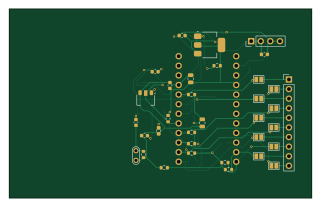
About the Ic202-frequency meter PCB
Ic202-frequency meter is an open source AVR/Arduino PCB design by joseluu, published on GitHub. It is a 2-layer board measuring 80 × 50 mm, with 38 components from 20 distinct parts.
Its main chip is the Pro Mini 3V3/8MHz, from the AVR/Arduino family. Other key parts include the AMS1117-5.0, AMS1117 (ADJ) and MB506. By type, the board carries 19 resistors, 12 capacitors, 3 ICs, 2 connectors, 1 module and 1 transistor.
From the project
Frequencemetre pour Icom IC-202 : prediviseur MB506, Arduino Pro Mini, afficheur 3 digits multiplexe. Projet KiCad.
Projet KiCad transcrit du schéma manuscrit, selon la description de docs/specifications.md. Deux versions du schéma existent dans docs/ : Schema.jpg, la première photo, et Schemapropre.jpg`, une reprise plus lisible qui a servi à corriger plusieurs valeurs mal lues sur la première.
Chaîne de mesure : entrée RF → prédiviseur MB506 → étage de mise en forme à transistor alimenté en 3 V → broche D5 d'un Arduino Pro Mini → afficheur LCD 3 digits 7 segments multiplexé, déporté au bout d'une nappe.
Main components on the Ic202-frequency meter
Ic202-frequency meter bill of materials (BOM)
38 components, 20 distinct parts — part numbers from the project's BOM.
| Qty | Part | Footprint | Refs |
|---|---|---|---|
| 1 | AMS1117-5.0 | SOT-223-3_TabPin2 | U1 |
| 1 | AMS1117 (ADJ) | SOT-223-3_TabPin2 | U2 |
| 1 | MB506 | SOIC-8_5.3x6.2mm_P1.27mm | U3 |
| 1 | Pro Mini 3V3/8MHz | Arduino_Pro_Mini_Header_2x12 | A1 |
| 1 | 2SC5551AE-TD-E | SOT-89-3 | Q1 |
| 1 | +12V IN (4 pins: 2x+12V, 2x GND) | PinHeader_1x04_P2.54mm_Vertical | J1 |
| 1 | LCD | PinHeader_1x10_P2.54mm_Vertical | J4 |
| 3 | 100N 100n | C_0603_1608Metric | C1, C3, C5 |
| 3 | 10U 10u | C_0805_2012Metric | C2, C4, C6 |
| 1 | 1n | C_0603_1608Metric | C7 |
| 4 | 100n | C_0603_1608Metric | C8, C9, C10, C11 |
| 1 | 1u | C_0805_2012Metric | C12 |
| 1 | 220R | R_0603_1608Metric | R1 |
| 1 | 300R | R_0603_1608Metric | R2 |
| 1 | 51R | R_0603_1608Metric | R3 |
| 3 | 3K3 3k3 | R_0603_1608Metric | R4, R17, R18 |
| 1 | 470R | R_0603_1608Metric | R6 |
| 10 | 100K 100k | R_0603_1608Metric | R7, R8, R9, R10, R11, R12, R13, R14 +2 |
| 1 | 2K2 | R_0603_1608Metric | R19 |
| 1 | 470K | R_0603_1608Metric | R20 |
Ic202-frequency meter design files
The KiCad project lives in the joseluu/ic202-frequency-meter repository on GitHub; these links point at the commit this page was built from.
Ic202-frequency meter: common questions
What microcontroller does the Ic202-frequency meter use?
The Ic202-frequency meter is built around the Pro Mini 3V3/8MHz, from the AVR/Arduino family.
How big is the Ic202-frequency meter PCB?
The Ic202-frequency meter measures 80 × 50 mm, has 2 copper layers and is 1.6 mm thick.
How many components are on the Ic202-frequency meter?
38 components, from 20 distinct parts, with part numbers taken from the project's own BOM. The full bill of materials is listed on this page.
Where can I download the Ic202-frequency meter design files?
From the joseluu/ic202-frequency-meter repository on GitHub, which has the KiCad layout and the BOM; the links under Design files point to each one.
Can I use the Ic202-frequency meter design in my own project?
The repository has no license, so all rights stay with joseluu. Use it as a reference, and ask the author before reusing the design.
Can I test firmware for the Ic202-frequency meter without the hardware?
Yes. HardLabs builds a simulation of the board from its netlist and BOM, so you can run and debug AVR/Arduino firmware against it before you order a PCB.
Similar boards
 AVR/Arduino
V4
stuartpittaway
30 × 50 mm38 parts2LCC-BY-NC-4.01.1k AVR/Arduino
ModuleV450
30 × 61.4 mm39 parts2LCC-BY-NC-4.01.1k AVR/Arduino
Easyduino Atmega
Hanqaqa
68.8 × 53.6 mm35 parts4LCERN-OHL-P-2.0746 AVR/Arduino
Easyduino Atmega Nano
43.4 × 18 mm30 parts4LCERN-OHL-P-2.0746 AVR/Arduino
UsbGpib
xyphro
54 × 15 mm21 parts2LMIT683 AVR/Arduino
Lumberjack
peej
284.7 × 94.2 mm149 parts2LMIT402