
FX-Pads

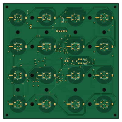
About the FX-Pads PCB
FX-Pads is an open source PCB design by jvegaf, published on GitHub. It is a 2-layer board measuring 100 × 100 mm, with 67 components from 10 distinct parts.
Other key parts include the HT16K33 24SOP. By type, the board carries 35 diodes, 16 switches, 9 capacitors, 5 resistors, 1 IC and 1 connector.
Main components on the FX-Pads
FX-Pads bill of materials (BOM)
67 components, 10 distinct parts.
| Qty | Part | Footprint | Refs |
|---|---|---|---|
| 1 | HT16K33 24SOP | SOIC-24W_7.5x15.4mm_P1.27mm | U1 |
| 1 | Conn_01x05 | JST_PH_S5B-PH-K_1x05_P2.00mm_Horizontal | J1 |
| 16 | SW_Push | sw-pad | SW1, SW2, SW3, SW4, SW5, SW6, SW7, SW8 +8 |
| 16 | WS2812B | LED_WS2812B_PLCC4_5.0x5.0mm_P3.2mm | D1, D2, D3, D4, D5, D6, D7, D8 +8 |
| 19 | 1N4148 | D_SOD-123 | D9, D18, D19, D20, D21, D22, D23, D24 +11 |
| 1 | 10uF | C_0805_2012Metric_Pad1.18x1.45mm_HandSolder | C1 |
| 8 | 1uF | C_0603_1608Metric_Pad1.08x0.95mm_HandSolder | C2, C3, C4, C5, C6, C7, C8, C9 |
| 1 | 330 | R_0805_2012Metric_Pad1.20x1.40mm_HandSolder | R1 |
| 2 | 47K | R_0805_2012Metric_Pad1.20x1.40mm_HandSolder | R2, R3 |
| 2 | 10K | R_0805_2012Metric_Pad1.20x1.40mm_HandSolder | R4, R5 |
FX-Pads design files
The KiCad project lives in the jvegaf/R3M1XXX repository on GitHub; these links point at the commit this page was built from.
FX-Pads: common questions
How big is the FX-Pads PCB?
The FX-Pads measures 100 × 100 mm, has 2 copper layers and is 1.6 mm thick.
How many components are on the FX-Pads?
67 components, from 10 distinct parts. The full bill of materials is listed on this page.
Where can I download the FX-Pads design files?
From the jvegaf/R3M1XXX repository on GitHub, which has the KiCad layout and the schematic; the links under Design files point to each one.
Can I use the FX-Pads design in my own project?
The repository has no license, so all rights stay with jvegaf. Use it as a reference, and ask the author before reusing the design.
More boards in R3M1XXX
 Raspberry Pi
R3M1XXX
50 × 110 mm180 parts2LNo license0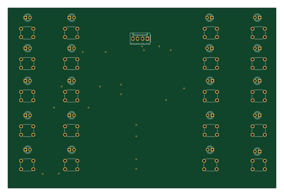
Deck bundle
140 × 94 mm68 parts2LNo license0
Ads7830
30.5 × 17.8 mm48 parts2LNo license0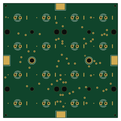
Trellis
60 × 60 mm37 parts2LNo license0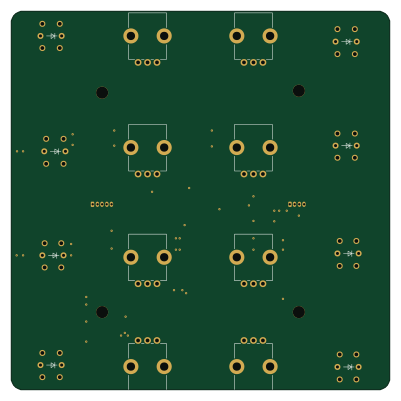
FX-Bundle
100 × 100 mm33 parts2LNo license0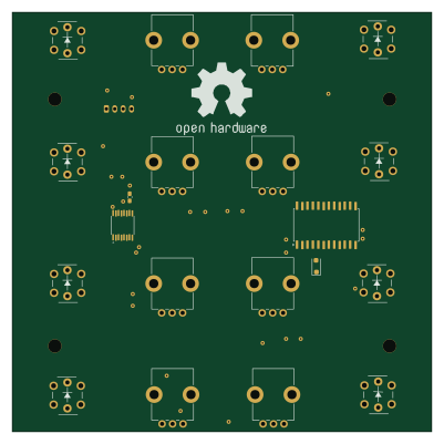
FX-Pots
100 × 100 mm33 parts2LNo license0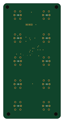
Deck-Btns
50 × 100 mm27 parts2LNo license0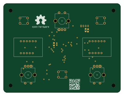 AVR/Arduino
Encoders-LCD
100 × 76 mm24 parts2LNo license0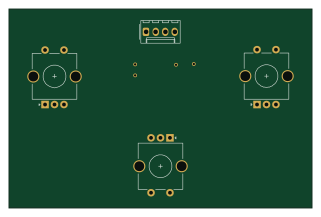 AVR/Arduino
Encoders i2c
80 × 52.5 mm8 parts2LNo license0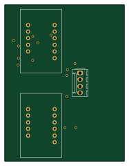
Lcd ht16k33
46 × 60 mm8 parts2LNo license0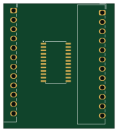
Ht16k33-adapter
41.5 × 46.5 mm3 parts2LNo license0