
Rover panel

About the Rover panel PCB
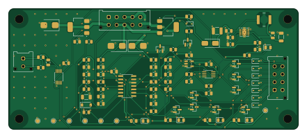
Rover panel is an open source PCB design by karimf1, published on GitHub under the MIT license. It is a 2-layer board measuring 110 × 46 mm, with 95 components from 43 distinct parts.
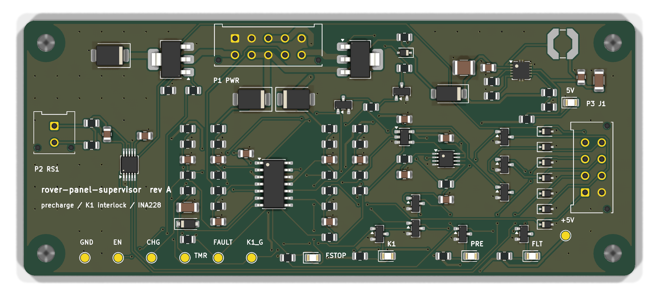
Other key parts include the LM5165XDRCR, INA228AIDGSR, LM339DR, SN74LVC1G08DBVR and SN74LVC1G74. By type, the board carries 38 resistors, 18 diodes, 18 capacitors, 12 transistors, 5 ICs and 3 connectors.
From the project
This repository is continuation of rover panel repo. Power panel PCB layout is implemented in KiCAD based of AutoCAD version of rover panel .
The PCB was missing. It sits on four standoffs on the panel plate, between the shunt and the signal connector, and does three jobs:
- precharge — it switches the pack through the panel's 22 Ω resistor R1 into the ESC bank, and holds contactor K1 open until the switched bus reaches ~90 % of the pack - interlock — K1's coil is energised through the E-stop loop and this board, so the board can open K1 but nothing on it can close K1 past an open E-stop - current sense — an INA228 on the panel's 0.75 mΩ shunt RS1, reported over I2C
Main components on the Rover panel
Rover panel bill of materials (BOM)
95 components, 43 distinct parts — part numbers from the project's BOM.
| Qty | Part | Footprint | Refs |
|---|---|---|---|
| 1 | LM5165XDRCR LM5165X Texas Instruments | Texas_S-PVSON-N10_ThermalVias | U1 |
| 1 | INA228AIDGSR INA228 Texas Instruments | VSSOP-10_3x3mm_P0.5mm | U2 |
| 1 | LM339DR LM339 | SOIC-14_3.9x8.7mm_P1.27mm | U3 |
| 1 | SN74LVC1G08DBVR 74LVC1G08 | SOT-23-5 | U4 |
| 1 | SN74LVC1G74 | SSOP-8_2.95x2.8mm_P0.65mm | U5 |
| 1 | NDT3055L | SOT-223-3_TabPin2 | Q1 |
| 10 | 2N7002K | SOT-23 | Q2, Q3, Q4, Q5, Q7, Q8, Q9, Q10 +2 |
| 1 | NDT2955 | SOT-223-3_TabPin2 | Q6 |
| 1 | Molex 43045-1012 P1 power/coil 2x05 | Molex_Micro-Fit_3.0_43045-1012_2x05_P3.00mm_Vertical | P1 |
| 1 | Molex 43045-0212 P2 Kelvin RS1 | Molex_Micro-Fit_3.0_43045-0212_2x01_P3.00mm_Vertical | P2 |
| 1 | Molex 43045-0812 P3 signal to J1 2x04 | Molex_Micro-Fit_3.0_43045-0812_2x04_P3.00mm_Vertical | P3 |
| 1 | SM6T36A | D_SMB | D1 |
| 1 | B160-13-F B160 | D_SMA | D2 |
| 1 | green 5V | LED_0805_2012Metric | D3 |
| 1 | 1N4148W | D_SOD-123 | D4 |
| 2 | SM6T36A | D_SMB | D5, D6 |
| 1 | BZX384-C12 | D_SOD-323 | D7 |
| 1 | green K1 | LED_0805_2012Metric | D8 |
| 1 | amber PRECHARGE | LED_0805_2012Metric | D9 |
| 1 | red FAULT | LED_0805_2012Metric | D10 |
Show 23 more
| Qty | Part | Footprint | Refs |
|---|---|---|---|
| 1 | red E-STOP OPEN | LED_0805_2012Metric | D11 |
| 7 | PESD5V0S1BA | D_SOD-323 | D12, D13, D14, D15, D16, D17, D18 |
| 1 | Coilcraft LPS5030-224MRB 220uH | L_Coilcraft_LPS5030 | L1 |
| 1 | 2u2 100V | C_1210_3225Metric | C1 |
| 1 | 100n 100V | C_0805_2012Metric | C2 |
| 1 | 22u 10V | C_1206_3216Metric | C3 |
| 11 | 100n 50V | C_0805_2012Metric | C4, C5, C6, C7, C8, C13, C14, C15 +3 |
| 3 | 10n 50V | C_0805_2012Metric | C9, C10, C12 |
| 1 | 10u 25V | C_1206_3216Metric | C11 |
| 5 | 1M | R_0805_2012Metric | R1, R16, R20, R23, R31 |
| 1 | 110k | R_0805_2012Metric | R2 |
| 2 | 0R | R_0805_2012Metric | R3, R4 |
| 5 | 1k5 | R_0805_2012Metric | R5, R35, R36, R37, R38 |
| 2 | 10R | R_0805_2012Metric | R6, R7 |
| 1 | 30k1 | R_0805_2012Metric | R8 |
| 12 | 10k | R_0805_2012Metric | R9, R10, R11, R19, R21, R24, R25, R26 +4 |
| 2 | 100k 0.1% | R_0805_2012Metric | R12, R14 |
| 1 | 9k76 0.1% | R_0805_2012Metric | R13 |
| 1 | 11k 0.1% | R_0805_2012Metric | R15 |
| 1 | 330k | R_0805_2012Metric | R17 |
| 3 | 100k | R_0805_2012Metric | R18, R22, R28 |
| 1 | 100R | R_0805_2012Metric | R30 |
| 1 | 47k | R_0805_2012Metric | R34 |
Rover panel design files
The KiCad project lives in the karimf1/rover-panel-pcb repository on GitHub; these links point at the commit this page was built from.
Rover panel: common questions
How big is the Rover panel PCB?
The Rover panel measures 110 × 46 mm, has 2 copper layers and is 1.6 mm thick.
How many components are on the Rover panel?
95 components, from 43 distinct parts, with part numbers taken from the project's own BOM. The full bill of materials is listed on this page.
Where can I download the Rover panel design files?
From the karimf1/rover-panel-pcb repository on GitHub, which has the KiCad layout, the schematic and the BOM; the links under Design files point to each one.
Can I use the Rover panel design in my own project?
Yes, under the terms of its MIT license, which karimf1 chose for the repository.