
Smart usb relay

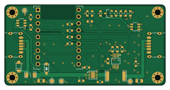
About the Smart usb relay PCB
Smart usb relay is an open source PCB design by Kostecki, published on GitHub. It is a 2-layer board measuring 60 × 30 mm, with 35 components from 20 distinct parts.
Other key parts include the TPS2557DRBR and INA226AIDGSR. By type, the board carries 19 resistors, 5 capacitors, 4 diodes, 2 ICs, 2 connectors and 1 transistor.
It belongs with the iot & wireless designs in this gallery.
From the project
Inline USB-C power switch + meter: ESP32-H2 SuperMini, ESPHome over Thread, JLC-assembled
An inline USB-C box that switches and meters 5 V power to a USB gadget (lamp, fan, sensor) from Home Assistant. Charger → box → device.
- ESP32-H2 SuperMini running ESPHome over Thread (OTA, no Wi-Fi) - TPS2557 current-limited switch (3 A), INA226 voltage/current/power metering → kWh in the Energy dashboard - USB-C in and out: fixed 5 V sink towards the charger, 1.5 A / 3 A source towards the device (follows what the charger offers) - 60 × 30 mm, 2 layers, assembled by JLCPCB (except the SuperMini, which sits on headers)
Main components on the Smart usb relay
Smart usb relay bill of materials (BOM)
35 components, 20 distinct parts.
| Qty | Part | Footprint | Refs |
|---|---|---|---|
| 1 | TPS2557DRBR | SON-8_L3.0-W3.0-P0.65-LS3.0-BL-EP | U2 |
| 1 | INA226AIDGSR | MSOP-10_L3.0-W3.0-P0.50-LS5.0-BL | U3 |
| 1 | AO3401A | SOT-23_L2.9-W1.3-P1.90-LS2.4-BR | Q1 |
| 1 | USB-C IN (TYPE-C-31-M-17) | USB_C_Receptacle_HRO_TYPE-C-31-M-17 | J1 |
| 1 | USB-C OUT (TYPE-C-31-M-17) | USB_C_Receptacle_HRO_TYPE-C-31-M-17 | J2 |
| 1 | 5A fast | F1206 | F1 |
| 1 | 10m 1% (WSLP2512) | R2512 | RS1 |
| 1 | SMF6.0A | SOD-123FL_L2.7-W1.8-LS3.8-RD | D1 |
| 2 | SRV05-4 | SOT-23-6_L2.9-W1.6-P0.95-LS2.8-BR | D2, D4 |
| 1 | B5819W | SOD-123_L2.7-W1.6-LS3.7-RD-1 | D3 |
| 2 | 10uF 25V | C_0805_2012Metric | C1, C5 |
| 3 | 100nF | C_0603_1608Metric | C2, C3, C4 |
| 2 | 5.1k | R_0603_1608Metric | R1, R2 |
| 4 | 1k | R_0603_1608Metric | R3, R4, R18, R19 |
| 4 | 100k | R_0603_1608Metric | R5, R6, R7, R15 |
| 1 | 33k | R_0603_1608Metric | R8 |
| 2 | 10k | R_0603_1608Metric | R9, R12 |
| 2 | 4.7k | R_0603_1608Metric | R10, R11 |
| 2 | 12k | R_0603_1608Metric | R13, R14 |
| 2 | 7.5k | R_0603_1608Metric | R16, R17 |
Smart usb relay design files
The KiCad project lives in the Kostecki/smart-usb-relay repository on GitHub; these links point at the commit this page was built from.
Smart usb relay: common questions
How big is the Smart usb relay PCB?
The Smart usb relay measures 60 × 30 mm, has 2 copper layers and is 1.6 mm thick.
How many components are on the Smart usb relay?
35 components, from 20 distinct parts. The full bill of materials is listed on this page.
Where can I download the Smart usb relay design files?
From the Kostecki/smart-usb-relay repository on GitHub, which has the KiCad layout and the schematic; the links under Design files point to each one.
Can I use the Smart usb relay design in my own project?
The repository has no license, so all rights stay with Kostecki. Use it as a reference, and ask the author before reusing the design.
Similar boards

EinkPDA screen
TalismanDesign
95 × 54 mm27 parts2LApache-2.02.0k
RPi RM0 WiFi/Bluetooth Module
schlae
11.1 × 14 mm76 parts6LNo license1.0k
L0 USB
Luos-io
20.3 × 15.3 mm19 parts2LMIT547
Breakout board
26.7 × 27.9 mm29 parts2LMIT547
Stm32f0 disco Luos shield
55.9 × 99.1 mm26 parts2LMIT547
L0 USBA
20.3 × 15.3 mm19 parts2LMIT547