
Agriculture-VCU v1

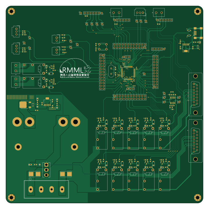
About the Agriculture-VCU v1 PCB
Agriculture-VCU v1 is an open source STM32 PCB design by laurapreidewe, published on GitHub. It is a 4-layer board measuring 180 × 180 mm, with 192 components from 51 distinct parts.
Its main chip is the STM32F446RET6, from the STM32 family. Other key parts include the TPS79533DCQ and LM358M/NOPB. By type, the board carries 62 resistors, 23 capacitors, 20 test points, 19 connectors, 16 LEDs and 16 diodes.
It belongs with the power & battery designs in this gallery.
From the project
STM32 based Vehicle control unit (VCU) PCB for agricultural machinery. Made with KiCad 8, now updated to KiCad 10
AgriVCU is an STM32F446RE-based vehicle control PCB derived from the Cultivator PCB. It provides relay control and interfaces for the main motor, pump motor, brakes, throttle signals, and peripheral modules.
The editable KiCad design in this repository is the corrected version. Previously printed AgriVCU v1 boards have a VCAP-to-3V3 connection error and require the trace-cut repair below. The Cultivator-to-AgriVCU v1 changes and this printed-board repair are separate revision history items.
Main components on the Agriculture-VCU v1
Agriculture-VCU v1 bill of materials (BOM)
192 components, 51 distinct parts.
| Qty | Part | Footprint | Refs |
|---|---|---|---|
| 2 | TPS79533DCQ | SOT127P706X180-6N | U1, U4 |
| 1 | STM32F446RET6 STM32F446RETx | LQFP-64_10x10mm_P0.5mm | U2 |
| 1 | LM358M/NOPB LM358 | SOIC-8_3.9x4.9mm_P1.27mm | U3 |
| 12 | BC846B,215 BC846 | SOT-23 | Q1, Q2, Q3, Q4, Q5, Q6, Q7, Q8 +4 |
| 1 | GT6K2P10KH | TO-252-2 | Q13 |
| 1 | ABL-8.000MHZ-B2 8.192MHz | Crystal_HC49-U_Vertical | Y1 |
| 1 | 1734035-3 USB_B_Mini | USB_Mini-B_Wuerth_65100516121_Horizontal | J1 |
| 1 | PH1-05-UA ST-LINKV2 | PinHeader_1x05_P2.54mm_Vertical | J2 |
| 1 | 61302621821 Conn_02x13_Odd_Even | PinSocket_2x13_P2.54mm_Vertical | J3 |
| 3 | PPTC122LFBN-RC Conn_02x12_Odd_Even | PinSocket_2x12_P2.54mm_Vertical | J4, J5, J6 |
| 1 | 691137710002 RELAY1_EXTERNAL | Wuerth_TBL_691137710002_1x02_P5mm | J7 |
| 1 | 691137710002 RELAY2_EXTERNAL | Wuerth_TBL_691137710002_1x02_P5mm | J8 |
| 1 | 1719710002 BRAKE1 | Molex_SL_171971-0002_1x02_P2.54mm_Vertical | J11 |
| 1 | 1719710002 BRAKE2 | Molex_SL_171971-0002_1x02_P2.54mm_Vertical | J12 |
| 2 | 61300611821 CAN_MCP2551 | PinSocket_1x06_P2.54mm_Vertical | J13, J14 |
| 1 | 691137710002 CAN1 TEST | Wuerth_TBL_691137710002_1x02_P5mm | J15 |
| 1 | 691137710002 CAN2 TEST | Wuerth_TBL_691137710002_1x02_P5mm | J16 |
| 1 | RS1-07-G SD CARD MODULE | PinSocket_1x07_P2.54mm_Vertical | J17 |
| 1 | 1719710003 USART | Molex_SL_171971-0003_1x03_P2.54mm_Vertical | J18 |
| 1 | 1719710003 ADC1_IN12 | Molex_SL_171971-0003_1x03_P2.54mm_Vertical | J19 |
Show 31 more
| Qty | Part | Footprint | Refs |
|---|---|---|---|
| 1 | 1719710003 ADC1_IN13 | Molex_SL_171971-0003_1x03_P2.54mm_Vertical | J20 |
| 1 | 0387206304 INPUT | Molex_38720-6304 | J21 |
| 2 | 0154010.DR | Fuseholder_Littelfuse_Nano2_154x | F1, F2 |
| 1 | 90120-0923 BOOT0MODE | PinHeader_1x03_P2.54mm_Vertical | JP1 |
| 1 | 90120-0923 BOOT1MODE | PinHeader_1x03_P2.54mm_Vertical | JP2 |
| 5 | JY-12H-K RELAY_MM | Relay_SPST_Fujitsu_JY-12H-K | K1, K2, K3, K4, K5 |
| 5 | JY-12H-K RELAY_PM | Relay_SPST_Fujitsu_JY-12H-K | K6, K7, K8, K9, K10 |
| 2 | JY-12H-K RELAY_EX | Relay_SPST_Fujitsu_JY-12H-K | K11, K12 |
| 1 | TL1105F160QWITHSTRAIGHT SW_SPST | SW_PUSH_6mm | SW1 |
| 1 | ANT11SECQE SW_SPDT | SW_500SSP1S1M2REA | SW2 |
| 15 | TestPoint | PinHeader_1x01_P2.54mm_Vertical | TP4, TP5, TP6, TP7, TP8, TP9, TP10, TP11 +7 |
| 5 | GND | PinHeader_1x01_P2.54mm_Vertical | TP19, TP20, TP21, TP22, TP23 |
| 16 | 150060SS75003 LED | LED_0603_1608Metric_Pad1.05x0.95mm_HandSolder | LED1, LED2, LED3, LED4, LED5, LED6, LED7, LED8 +8 |
| 3 | DESD5V0U1BA DESD5V0U1BA-7 | SOD323-L_DIO-M | D1, D2, D3 |
| 12 | 1N4148W-TP 1N4148 | D_SOD-123 | D4, D5, D6, D7, D8, D9, D10, D11 +4 |
| 1 | PLZ4V7C PLZ4V7C-G3/H | CR_PLZ5V1C_VIS-L | D16 |
| 4 | 0603YC105JAT2A 1u | C_0603_1608Metric_Pad1.08x0.95mm_HandSolder | C1, C3, C21, C23 |
| 2 | KGM15AR51E103KT 0.01u | C_0603_1608Metric_Pad1.08x0.95mm_HandSolder | C2, C22 |
| 2 | 06035A220JAT2A 22p | C_0603_1608Metric_Pad1.08x0.95mm_HandSolder | C4, C5 |
| 2 | GRM155R70J105KA12D 1u | C_0402_1005Metric_Pad0.74x0.62mm_HandSolder | C6, C13 |
| 6 | GRM155R71C104KA88J 100n | C_0402_1005Metric_Pad0.74x0.62mm_HandSolder | C7, C9, C10, C11, C12, C14 |
| 1 | GRM155R61A106ME11D 10u | C_0402_1005Metric_Pad0.74x0.62mm_HandSolder | C8 |
| 6 | KGM15BR71H104KT 100n | C_0603_1608Metric_Pad1.08x0.95mm_HandSolder | C15, C16, C17, C18, C19, C20 |
| 2 | CPF0603B300RE1 300 | R_0603_1608Metric_Pad0.98x0.95mm_HandSolder | R1, R59 |
| 4 | RT0402FRE0710KL 10k | R_0402_1005Metric_Pad0.72x0.64mm_HandSolder | R2, R3, R4, R62 |
| 33 | RT0603FRE0710KL 10k | R_0603_1608Metric_Pad0.98x0.95mm_HandSolder | R5, R6, R7, R9, R10, R12, R13, R15 +25 |
| 13 | RT0603FRE131KL 1k | R_0603_1608Metric_Pad0.98x0.95mm_HandSolder | R8, R11, R14, R17, R20, R23, R26, R29 +5 |
| 2 | RT0603FRE13120RL 120 | R_0603_1608Metric_Pad0.98x0.95mm_HandSolder | R42, R43 |
| 4 | RP0603BRD075K1L 5k1 | R_0603_1608Metric_Pad0.98x0.95mm_HandSolder | R46, R49, R54, R56 |
| 3 | RP0603BRD07100RL 100 | R_0603_1608Metric_Pad0.98x0.95mm_HandSolder | R50, R52, R60 |
| 1 | RT0603FRE07470RL 470 | R_0603_1608Metric_Pad0.98x0.95mm_HandSolder | R58 |
Agriculture-VCU v1 design files
The KiCad project lives in the laurapreidewe/Agriculture-VCU_v1 repository on GitHub; these links point at the commit this page was built from.
- LayoutTractor VCU.kicad_pcb
- SchematicTractor VCU.kicad_sch
Agriculture-VCU v1: common questions
What microcontroller does the Agriculture-VCU v1 use?
The Agriculture-VCU v1 is built around the STM32F446RET6, from the STM32 family.
How big is the Agriculture-VCU v1 PCB?
The Agriculture-VCU v1 measures 180 × 180 mm, has 4 copper layers and is 2 mm thick.
How many components are on the Agriculture-VCU v1?
192 components, from 51 distinct parts. The full bill of materials is listed on this page.
Where can I download the Agriculture-VCU v1 design files?
From the laurapreidewe/Agriculture-VCU_v1 repository on GitHub, which has the KiCad layout and the schematic; the links under Design files point to each one.
Can I use the Agriculture-VCU v1 design in my own project?
The repository has no license, so all rights stay with laurapreidewe. Use it as a reference, and ask the author before reusing the design.
Can I test firmware for the Agriculture-VCU v1 without the hardware?
Yes. HardLabs builds a simulation of the board from its netlist and BOM, so you can run and debug STM32 firmware against it before you order a PCB.
Similar boards
 STM32
LumenPnP Motherboard
opulo-inc
149 × 95 mm296 parts4LCC-BY-SA-4.03.7k STM32
Type g
google
169 × 30 mm24 parts2LApache-2.02.9k STM32
Base
52.3 × 52.3 mm36 parts2LApache-2.02.9k STM32
Main panel
234 × 84 mm26 parts4LApache-2.02.9k STM32
Type a
150 × 30 mm14 parts2LApache-2.02.9k STM32
Type c
188 × 30 mm17 parts2LApache-2.02.9k