
Controls-Leader

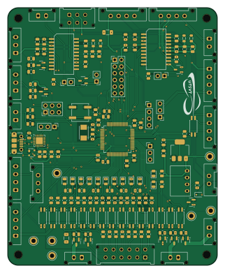
About the Controls-Leader PCB
Controls-Leader is an open source STM32 PCB design by lhr-solar, published on GitHub. It is a 2-layer board measuring 79.3 × 97.5 mm, with 177 components from 81 distinct parts.
Its main chip is the STM32F413RHTX, from the STM32 family. Other key parts include the EL3H7, RI3-1205S, NCP1117-3.3_SOT223, ADM3055E and CDSOT23-T24CAN. By type, the board carries 53 resistors, 35 capacitors, 24 ICs, 23 connectors, 16 diodes and 7 test points.
Main components on the Controls-Leader
Controls-Leader bill of materials (BOM)
177 components, 81 distinct parts — part numbers from the project's BOM.
| Qty | Part | Footprint | Refs |
|---|---|---|---|
| 16 | EL3H7 | SSOP-4_4.4x2.6mm_P1.27mm | U1, U2, U3, U4, U5, U6, U8, U9 +8 |
| 1 | STM32F413RHTX STM32F413RHTx | LQFP-64_10x10mm_P0.5mm | U7 |
| 1 | RI3-1205S | RI3_DC_Converter | U12 |
| 1 | NCP1117-3.3_SOT223 | SOT-223-3_TabPin2 | U13 |
| 2 | ADM3055E | SOIC-20W_7.5x15.4mm_Pitch1.27mm | U14, U17 |
| 2 | CDSOT23-T24CAN | SOT-23-3 | U15, U18 |
| 1 | CP2102N-A01-GQFN24 | QFN-24-1EP_4x4mm_P0.5mm_EP2.6x2.6mm | U19 |
| 6 | IRLML0030 | SOT-23 | Q1, Q2, Q3, Q4, Q5, Q6 |
| 1 | Crystal | Crystal_SMD_TXC_7A-2Pin_5x3.2mm | Y1 |
| 1 | ExtraADCs | Molex_MicroFit3.0_1x3xP3.00mm_PolarizingPeg_Vertical | J1 |
| 3 | UART_TP | PinHeader_1x03_P2.54mm_Vertical | J2, J13, J25 |
| 1 | ExtraGPIO_Conn | PinHeader_2x06_P2.54mm_Vertical | J3 |
| 1 | Dashboard | Molex_MicroFit3.0_2x6xP3.00mm_PolarizingPeg_Vertical | J4 |
| 1 | M_CAN_IN | Molex_Micro-Fit_3.0_43045-0612_2x03_P3.00mm_Vertical | J5 |
| 1 | Display | Molex_Micro-Fit_3.0_43650-0415_1x04_P3.00mm_Vertical | J6 |
| 1 | Accel_Pot | Molex_Micro-Fit_3.0_43650-0315_1x03_P3.00mm_Vertical | J7 |
| 1 | SWD | PinHeader_1x04_P2.54mm_Vertical | J8 |
| 1 | Brake_Pot | Molex_Micro-Fit_3.0_43650-0315_1x03_P3.00mm_Vertical | J9 |
| 1 | A_PRCHG_BYPASS | Molex_Micro-Fit_3.0_43650-0415_1x04_P3.00mm_Vertical | J10 |
| 1 | M_PRCHG_BYPASS | Molex_Micro-Fit_3.0_43650-0415_1x04_P3.00mm_Vertical | J11 |
Show 61 more
| Qty | Part | Footprint | Refs |
|---|---|---|---|
| 1 | Brake_Sw | Molex_Micro-Fit_3.0_43650-0215_1x02_P3.00mm_Vertical | J12 |
| 1 | CAN_DB9 | Molex_Micro-Fit_3.0_43650-0215_1x02_P3.00mm_Vertical | J14 |
| 1 | CONN_02X03_ODD_EVEN Conn_02x03_Odd_Even | PinHeader_2x03_P2.54mm_Vertical | J15 |
| 1 | M_CAN_DB9 | Molex_Micro-Fit_3.0_43650-0215_1x02_P3.00mm_Vertical | J16 |
| 1 | M_CNTCTR | Molex_Micro-Fit_3.0_43650-0415_1x04_P3.00mm_Vertical | J17 |
| 1 | PowerConn | Molex_MicroFit3.0_1x2xP3.00mm_PolarizingPeg_Vertical | J18 |
| 1 | CAN_IN | Molex_MicroFit3.0_1x4xP3.00mm_PolarizingPeg_Vertical | J21 |
| 1 | CAN_OUT | Molex_MicroFit3.0_1x4xP3.00mm_PolarizingPeg_Vertical | J22 |
| 1 | USB_B_Micro | USB_Micro-B_Molex-105017-0001 | J23 |
| 1 | CAN_TP | PinHeader_1x02_P2.54mm_Vertical | J27 |
| 1 | EXTERNAL_BRAKELIGHT | Molex_Micro-Fit_3.0_43650-0215_1x02_P3.00mm_Vertical | BRAKELIGHT1 |
| 2 | Fuse | Fuse_1206_3216Metric | F1, F2 |
| 2 | Termination Resistors | PinHeader_1x02_P2.54mm_Vertical | JP1, JP2 |
| 1 | EXTERNAL_LEFTBLINK | Molex_Micro-Fit_3.0_43650-0215_1x02_P3.00mm_Vertical | L_BLINK_EXT1 |
| 1 | EXTERNAL_RIGHTBLINK | Molex_Micro-Fit_3.0_43650-0215_1x02_P3.00mm_Vertical | R_BLINK_EXT1 |
| 1 | RESET | SW_SPST_B3SL-1002P | SW10 |
| 1 | +5V_TP | TestPoint_Keystone_5005-5009_Compact | TP4 |
| 1 | GND_TP | TestPoint_Keystone_5005-5009_Compact | TP5 |
| 1 | +3.3V_TP | TestPoint_Keystone_5005-5009_Compact | TP6 |
| 1 | RIGHT_BLINK | TestPoint_Keystone_5005-5009_Compact | TP7 |
| 1 | LEFT_BLINK | TestPoint_Keystone_5005-5009_Compact | TP8 |
| 1 | 12V_UNISO | TestPoint_Keystone_5005-5009_Compact | TP9 |
| 1 | GND_UNISO | TestPoint_Keystone_5005-5009_Compact | TP10 |
| 1 | Cruise Ind | LED_0805_2012Metric | D1 |
| 2 | BAS70-04 | SOT-23 | D2, D3 |
| 1 | M_CNCTR | LED_0805_2012Metric | D4 |
| 1 | MPB_CNCTR | LED_0805_2012Metric | D7 |
| 2 | PowerOn | LED_0805_2012Metric | D8, D14 |
| 1 | OS Error | LED_0805_2012Metric | D9 |
| 1 | Motor Controller Fault | LED_0805_2012Metric | D10 |
| 1 | Ignition 1 | LED_0805_2012Metric | D11 |
| 1 | Ignition 2 | LED_0805_2012Metric | D12 |
| 1 | BPS Fault | LED_0805_2012Metric | D13 |
| 1 | SP0503BAHTG | SOT-143 | D15 |
| 1 | Control Fault | LED_0805_2012Metric | D16 |
| 1 | SD12_SOD323 | D_SOD-323 | D17 |
| 1 | APB_CNCTR | LED_0805_2012Metric | D18 |
| 4 | 1.8K 1.8k | L_0805_2012Metric | L5, L6, L7, L8 |
| 2 | 1UF 1uF | C_0805_2012Metric | C1, C15 |
| 3 | 10U 10u | C_0805_2012Metric | C4, C21, C22 |
| 6 | 100NF 100nF | C_0805_2012Metric | C5, C6, C9, C11, C12, C14 |
| 2 | 12PF 12pF | C_0805_2012Metric | C7, C8 |
| 3 | 4.7UF 4.7uF | C_0805_2012Metric | C10, C13, C41 |
| 9 | 0.1UF 0.1uF | C_0805_2012Metric | C16, C17, C24, C25, C29, C34, C35, C39 +1 |
| 4 | 10UF 10uF | C_0805_2012Metric | C23, C28, C33, C38 |
| 4 | 0.01UF 0.01uF | C_0805_2012Metric | C26, C30, C36, C40 |
| 2 | 0.22UF 0.22uF | C_0805_2012Metric | C27, C37 |
| 10 | 698 | R_0805_2012Metric | R1, R2, R3, R4, R8, R9, R28, R30 +2 |
| 8 | 2k | R_0805_2012Metric | R5, R10, R39, R52, R55, R60, R62, R64 |
| 5 | 510 | R_0805_2012Metric | R6, R11, R12, R19, R22 |
| 2 | 5.1K 5.1k | R_0805_2012Metric | R7, R13 |
| 6 | 100K 100k | R_0805_2012Metric | R14, R20, R23, R41, R56, R58 |
| 7 | 4.9K 4.9k | R_0805_2012Metric | R15, R33, R50, R53, R59, R61, R63 |
| 4 | 10K 10k | R_0805_2012Metric | R16, R18, R26, R27 |
| 2 | 0 | R_0805_2012Metric | R17, R34 |
| 2 | 120 | R_0805_2012Metric | R21, R35 |
| 3 | 105R | R_0805_2012Metric | R24, R25, R32 |
| 1 | 1.5K 1.5k | R_0805_2012Metric | R29 |
| 1 | 22.1K 22.1k | R_0805_2012Metric | R36 |
| 1 | 47.5K 47.5k | R_0805_2012Metric | R37 |
| 1 | 1k | R_0805_2012Metric | R38 |
Controls-Leader design files
The KiCad project lives in the lhr-solar/Controls-LeaderPCB repository on GitHub; these links point at the commit this page was built from.
- LayoutControls-Leader.kicad_pcb
- SchematicControls-Leader.kicad_sch
- BOMproduction/bom.csv
Controls-Leader: common questions
What microcontroller does the Controls-Leader use?
The Controls-Leader is built around the STM32F413RHTX, from the STM32 family.
How big is the Controls-Leader PCB?
The Controls-Leader measures 79.3 × 97.5 mm, has 2 copper layers and is 1.6 mm thick.
How many components are on the Controls-Leader?
177 components, from 81 distinct parts, with part numbers taken from the project's own BOM. The full bill of materials is listed on this page.
Where can I download the Controls-Leader design files?
From the lhr-solar/Controls-LeaderPCB repository on GitHub, which has the KiCad layout, the schematic and the BOM; the links under Design files point to each one.
Can I use the Controls-Leader design in my own project?
The repository has no license, so all rights stay with lhr-solar. Use it as a reference, and ask the author before reusing the design.
Can I test firmware for the Controls-Leader without the hardware?
Yes. HardLabs builds a simulation of the board from its netlist and BOM, so you can run and debug STM32 firmware against it before you order a PCB.
Similar boards
 STM32
STM32AxxSolder
AxxAxx
39 × 82.5 mm122 parts2LGPL-3.01.7k STM32
STM32AIOC
skuep
21 × 31.5 mm47 parts2LMIT1.4k STM32
STM32Ferris
pierrechevalier83
208.8 × 86.8 mm102 parts2LSHL-2.11.3k STM32
STM32Module 16S
stuartpittaway
71.1 × 89.6 mm113 parts4LCC-BY-NC-4.01.1k STM32
STM32Djinn
tzarc
192.3 × 150.5 mm216 parts2LCERN-OHL-S-2.0988 STM32
STM32Ghoul
228.6 × 79.4 mm163 parts2LCERN-OHL-S-2.0988