
LED controller

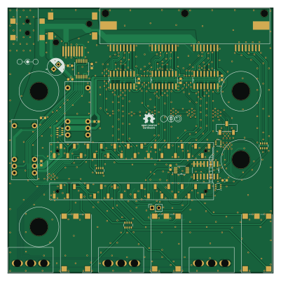
About the LED controller PCB
LED controller is an open source NXP PCB design by Llamero, published on GitHub under the CC-BY-SA-4.0 license. It is a 2-layer board measuring 100 × 100 mm, with 38 components from 18 distinct parts.
Its main chip is the Teensy4.1, from the NXP family. Other key parts include the 4x Gate Driver, 3x Analog Switch, 3x 10-Bit DAC and 3x Level Shifter. By type, the board carries 12 capacitors, 7 ICs, 5 connectors, 4 resistors, 3 switches and 2 diodes.
From the project
LED mount that is compatible with the Thorlabs 30 mm cage plate
The LEDs on the board are closely spaced so that all four LEDs efficiently couple into a 5 mm liquid light guide or other optical paths.
Each board can drive up to four individual LEDs, and includes a thermistor for temperature monitoring. The the LED current is regulated by an AL8843, allowing LEDs to be driven with up to three amps of current. The AL8843 also allows for both PWM control as well as analog current control down to 10% of the current limit (see below for setting max current limit).
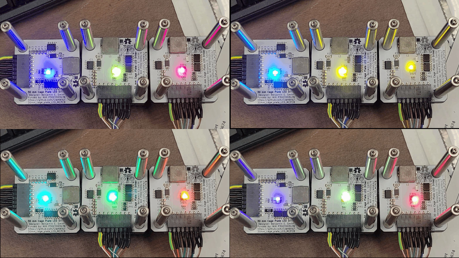
Main components on the LED controller
LED controller bill of materials (BOM)
38 components, 18 distinct parts — part numbers from the project's BOM.
| Qty | Part | Footprint | Refs |
|---|---|---|---|
| 3 | 4x Gate Driver Texas Instruments | D16-4x gate driver | U1, U2, U3 |
| 1 | Teensy4.1 SparkFun Electronics | Teensy_3_6_with_headers | U4 |
| 1 | 3x Analog Switch Texas Instruments | SN74LV4053ADR | U5 |
| 1 | 3x 10-Bit DAC Texas Instruments | DAC084S085CIMMXNOPB | U6 |
| 1 | 3x Level Shifter Nexperia USA Inc. | TSSOP14_NXB0104_NEX | U7 |
| 1 | Barrel_Jack_Switch Tensility International Corp | DC-jack_54-00165 | J1 |
| 1 | 4x RJ45 Amphenol ICC (Commercial Products) | RJ45_x4-RJSSE-5380-04 | J2 |
| 1 | 8P8C_Shielded Amphenol ICC (Commercial Products) | 1x RJ45 | J5 |
| 1 | Conn_01x03_Socket Harwin Inc. | PinSocket_1x03_P2.54mm_Vertical_SMD_Pin1Left | J6 |
| 1 | Conn_01x02_Socket Adam Tech | PinSocket_1x02_P2.54mm_Vertical | J7 |
| 2 | 15V DC-DC Diwell Electronics | SRS-1215-2 | PS1, PS2 |
| 3 | 10k TT Electronics/BI | P160KN2-4QC20B10K | RV1, RV2, RV3 |
| 3 | ELUMOASAQ2C22 C&K | ELUMOASAQ2C22_CNK | SW1, SW2, SW3 |
| 2 | BAT54BRW Diodes Incorporated | SOT-363_SC-70-6 | D1, D2 |
| 11 | 1µF Samsung Electro-Mechanics | C_0603_1608Metric | C1, C2, C3, C4, C5, C6, C7, C8 +3 |
| 1 | 220µF Rubycon | CP_Radial_D6.3mm_P2.50mm | C12 |
| 3 | 3600 Bourns Inc. | R_Array_Convex_4x0603 | RN1, RN2, RN4 |
| 1 | 390 YAGEO | R_Array_Convex_4x0603 | RN3 |
LED controller design files
The KiCad project lives in the Llamero/30mm_cage_plate_LED_MCPCB repository on GitHub; these links point at the commit this page was built from.
LED controller: common questions
What microcontroller does the LED controller use?
The LED controller is built around the Teensy4.1, from the NXP family.
How big is the LED controller PCB?
The LED controller measures 100 × 100 mm, has 2 copper layers and is 1.6 mm thick.
How many components are on the LED controller?
38 components, from 18 distinct parts, with part numbers taken from the project's own BOM. The full bill of materials is listed on this page.
Where can I download the LED controller design files?
From the Llamero/30mm_cage_plate_LED_MCPCB repository on GitHub, which has the KiCad layout, the schematic and the BOM; the links under Design files point to each one.
Can I use the LED controller design in my own project?
Yes, under the terms of its CC-BY-SA-4.0 license, which Llamero chose for the repository.
Can I test firmware for the LED controller without the hardware?
Yes. HardLabs builds a simulation of the board from its netlist and BOM, so you can run and debug NXP firmware against it before you order a PCB.
More boards in 30mm_cage_plate_LED_MCPCB
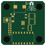
Similar boards
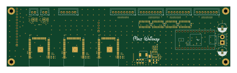 NXP
NXPMega-Cube-Board
MaltWhiskey
200 × 54 mm100 parts4LNo license763 NXP
NXP32Bit shift register
100 × 54 mm56 parts4LNo license763 NXP
NXPIC60
kiibohd
285 × 95 mm242 partsCERN-OHL-1.2415 NXP
NXPICED-R
175.4 × 145 mm163 partsCERN-OHL-1.2415 NXP
NXPTestcontroller
145.8 × 42.9 mm45 parts2LCERN-OHL-1.2415 NXP
NXPICED-L
175.4 × 145 mm163 partsCERN-OHL-1.2415