
Four Channel MHz LED Driver

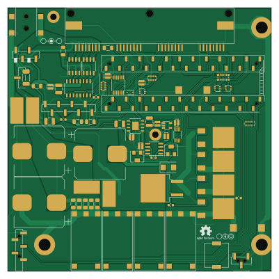
About the Four Channel MHz LED Driver PCB
Four Channel MHz LED Driver is an open source NXP PCB design by Llamero, published on GitHub. It is a 2-layer board measuring 100 × 100 mm, with 93 components from 47 distinct parts.
Its main chip is the Teensy3.6, from the NXP family. Other key parts include the 12V boost, SN74LV4T125PWR, DPBW06F-05, TMUX1204DGSR and BDJ0GA5WEFJ-E2. By type, the board carries 22 capacitors, 11 ICs, 11 resistors, 10 connectors, 6 jumpers and 5 switches.
From the project
High Speed Four Channel LED Driver that can run up to 30A
Main components on the Four Channel MHz LED Driver
Four Channel MHz LED Driver bill of materials (BOM)
93 components, 47 distinct parts — part numbers from the project's BOM.
| Qty | Part | Footprint | Refs |
|---|---|---|---|
| 1 | 12V boost | 12V_DC-DC_with_header_2117 | U1 |
| 1 | SN74LV4T125PWR | SN74LV4T125 | U2 |
| 1 | DPBW06F-05 | DPBW06F-05_with_header | U3 |
| 1 | TMUX1204DGSR | TMUX1204DGSR | U4 |
| 1 | BDJ0GA5WEFJ-E2 | BDJ0GA5WEFJ-E2 | U5 |
| 1 | ADP7182AUJZ-1.8-R7 | TSOT-23-5 | U6 |
| 1 | LT6200CS8-10 | SOIC-8_3.9x4.9mm_P1.27mm | U7 |
| 2 | IRF9358TRPBF | SO-8_3.9x4.9mm_P1.27mm | U8, U9 |
| 1 | Teensy3.6 | Teensy_3_6_with_headers | U12 |
| 1 | EL7457CSZ-T7 | EL7457CS | U13 |
| 1 | Fan_4pin | 4-pin_fan_SMD | M1 |
| 1 | SUM70060E | TO-263-2 | Q1 |
| 1 | Barrel_Jack_Switch | DC-jack_54-00165 | J1 |
| 1 | Conn_01x02_Female | Wire_Pad | J2 |
| 1 | 8P8C_Shielded_x4 | RJ45_x4-RJSSE-5380-04 | J3 |
| 1 | Conn_01x03_Male | Ref_only | J4 |
| 2 | Conn_01x03_Female | Ref_only | J5, J7 |
| 1 | Conn_01x08_Female | Ref_only | J6 |
| 1 | Conn_01x05_Female | Ref_only | J8 |
| 2 | Conn_01x24_Female | Ref_only | J9, J10 |
Show 27 more
| Qty | Part | Footprint | Refs |
|---|---|---|---|
| 1 | CPT-2016-75-SMT-TR | SMT-0940-T-3V-R_9x9_alarm | BZ1 |
| 7 | MountingHole_Pad | Ref_only | H1, H2, H4, H5, H6, H8, H10 |
| 1 | MountingHole_Pad | NF-A9_with_standoffs_and_bolts | H3 |
| 2 | MountingHole_Pad | M2_standoff_ground_via | H7, H9 |
| 4 | HS-PCB | Heatsink_910-40-2-23-2-B-0 | HS1, HS2, HS3, HS4 |
| 1 | LED wire | L-Wire_Pad | JP1 |
| 1 | Jumper_NC_Small | R_2010_5025Metric | JP2 |
| 2 | Jumper_NC_Small | R_1206_3216Metric | JP3, JP6 |
| 2 | Jumper_NC_Small | 20A_shunt_5104 | JP4, JP5 |
| 1 | R_POT | Pot_with_header | RV1 |
| 2 | R_POT_TRIM | 3224W-1-502E | RV2, RV3 |
| 4 | Pushbutton_with_LED | Pushbutton_LED-ELUMOATHQ3C12 | SW1, SW2, SW3, SW4 |
| 1 | SW_SPDT | 1x5_header_SSM-105-L-SV-BE-LC | SW5 |
| 2 | Thermistor | R_0603_1608Metric | TH1, TH2 |
| 3 | BAT54BRW | SOT-363_SC-70-6 | D1, D2, D3 |
| 1 | D_Zener | D_SOD-323 | D4 |
| 1 | TVS_Diode | DO-214AA | D5 |
| 1 | 10uH | L_1210_3225Metric | L1 |
| 3 | 7500uF | CP_Elec_18x22-EEE-FK1C752SV | C1, C2, C3 |
| 8 | 47uF | C_1206_3216Metric | C4, C5, C6, C7, C8, C10, C13, C14 |
| 8 | 2.2uF | 0508_Capacitor | C9, C15, C16, C17, C18, C19, C20, C22 |
| 3 | 2200pF | C_0603_1608Metric | C11, C12, C21 |
| 3 | 12 | R_1210_3225Metric | R1, R2, R7 |
| 4 | 5 | TO-252_resistor | R3, R4, R5, R6 |
| 1 | 150 | EXB-2HV151JV-1605x8 | RN1 |
| 2 | 200 | R_Array_Convex_4x0612 | RN2, RN4 |
| 1 | 4.7k | 1506-EXB-2HV472JV-for_2_oz_pour | RN3 |
Four Channel MHz LED Driver design files
The KiCad project lives in the Llamero/Four_Channel_MHz_LED_Driver repository on GitHub; these links point at the commit this page was built from.
Four Channel MHz LED Driver: common questions
What microcontroller does the Four Channel MHz LED Driver use?
The Four Channel MHz LED Driver is built around the Teensy3.6, from the NXP family.
How big is the Four Channel MHz LED Driver PCB?
The Four Channel MHz LED Driver measures 100 × 100 mm, has 2 copper layers and is 1.6 mm thick.
How many components are on the Four Channel MHz LED Driver?
93 components, from 47 distinct parts, with part numbers taken from the project's own BOM. The full bill of materials is listed on this page.
Where can I download the Four Channel MHz LED Driver design files?
From the Llamero/Four_Channel_MHz_LED_Driver repository on GitHub, which has the KiCad layout and the BOM; the links under Design files point to each one.
Can I use the Four Channel MHz LED Driver design in my own project?
The repository has no license, so all rights stay with Llamero. Use it as a reference, and ask the author before reusing the design.
Can I test firmware for the Four Channel MHz LED Driver without the hardware?
Yes. HardLabs builds a simulation of the board from its netlist and BOM, so you can run and debug NXP firmware against it before you order a PCB.
Similar boards
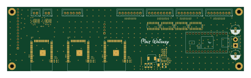 NXP
NXPMega-Cube-Board
MaltWhiskey
200 × 54 mm100 parts4LNo license763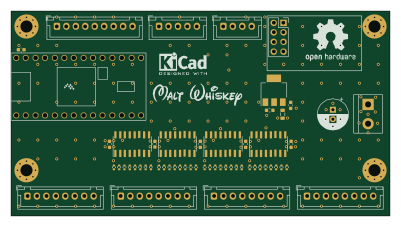 NXP
NXP32Bit shift register
100 × 54 mm56 parts4LNo license763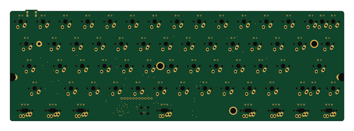 NXP
NXPIC60
kiibohd
285 × 95 mm242 partsCERN-OHL-1.2415 NXP
NXPICED-R
175.4 × 145 mm163 partsCERN-OHL-1.2415 NXP
NXPTestcontroller
145.8 × 42.9 mm45 parts2LCERN-OHL-1.2415 NXP
NXPICED-L
175.4 × 145 mm163 partsCERN-OHL-1.2415