
Small PCB to test 3.7 to 5V booster converter

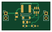
About the Small PCB to test 3.7 to 5V booster converter
Small PCB to test 3.7 to 5V booster converter is an open source PCB design by martinberlin, published on GitHub under the CERN-OHL-W-2.0 license. It is a 2-layer board measuring 25 × 14.7 mm, with 7 components from 6 distinct parts.
Other key parts include the C2932326. By type, the board carries 2 capacitors, 2 resistors, 1 IC, 1 diode and 1 inductor.
It belongs with the iot & wireless, power & battery and displays & leds designs in this gallery.
From the project
CINWRITE pcb is the Hardware repository for the HAT that provides GoodDisplay DEXA-C097 controller a fast way to talk SPI and 5V boost converter. The goal of this HAT is to provide WiFi, Bluetooth, RTC and extra I2C connector for sensors
Hardware repository for Cinwrite PCB, a HAT for 9.7 inch parallel epaper display controller DEXA-C097 sold by Good display which uses IT8951 as epaper timings controller and display engine.
This hardware is open source and you can use it commercially or modify it for your own purpouses according to the terms specified in the License. The only restriction is that it should be not mass produced and not sold without the permission of the Licensor.

Main components on the Small PCB to test 3.7 to 5V booster converter
Small PCB to test 3.7 to 5V booster converter bill of materials (BOM)
7 components, 6 distinct parts — part numbers from the project's BOM.
| Qty | Part | Footprint | Refs |
|---|---|---|---|
| 1 | C2932326 MT3608 | SOT-23-6 | U1 |
| 1 | C8598 1N5817 | D_SOD-123 | D1 |
| 1 | C68434 22uH | SWPA5040S282MT | L1 |
| 2 | C1644 22uF | C_0805_2012Metric | C1, C2 |
| 1 | C25805 110K | R_0603_1608Metric | R1 |
| 1 | C22809 15K | R_0603_1608Metric | R2 |
Small PCB to test 3.7 to 5V booster converter design files
The KiCad project lives in the martinberlin/H-cinread-it8951 repository on GitHub; these links point at the commit this page was built from.
Small PCB to test 3.7 to 5V booster converter: common questions
How big is the Small PCB to test 3.7 to 5V booster converter?
The Small PCB to test 3.7 to 5V booster converter measures 25 × 14.7 mm, has 2 copper layers and is 1.6 mm thick.
How many components are on the Small PCB to test 3.7 to 5V booster converter?
7 components, from 6 distinct parts, with part numbers taken from the project's own BOM. The full bill of materials is listed on this page.
Where can I download the Small PCB to test 3.7 to 5V booster converter design files?
From the martinberlin/H-cinread-it8951 repository on GitHub, which has the KiCad layout, the schematic and the BOM; the links under Design files point to each one.
Can I use the Small PCB to test 3.7 to 5V booster converter design in my own project?
Yes, under the terms of its CERN-OHL-W-2.0 license, which martinberlin chose for the repository.
More boards in H-cinread-it8951
Similar boards

Strip10
atopile
33.6 × 2 mm20 parts2LMIT4.0k
Grid10x10
33.6 × 35.5 mm200 parts4LMIT4.0k
Sub
3 parts2LMIT4.0k
Display Carrier
AxxAxx
35.6 × 58.2 mm5 parts2LGPL-3.01.7k
TemperaturePCB PANEL
stuartpittaway
116 × 75.5 mm178 parts2LCC-BY-NC-4.01.1k
Module 16S PassiveBalanceAddOn
61 × 74 mm86 parts2LCC-BY-NC-4.01.1k