
Power-Testing-Board

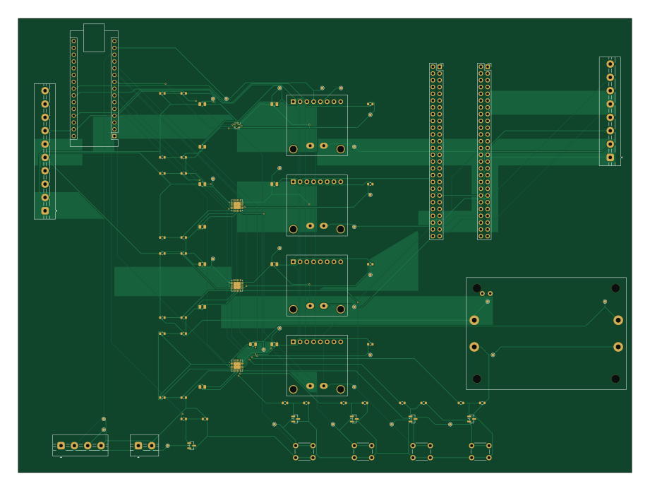
About the Power-Testing-Board
Power-Testing-Board is an open source AVR/Arduino PCB design by MatthewBasha, published on GitHub. It is a 4-layer board measuring 230 × 170 mm, with 67 components from 46 distinct parts.
Its main chip is the Arduino Nano USB-powered socket, from the AVR/Arduino family. Other key parts include the CUSTOMER_SUPPLIED_OR_VERIFY_LCSC, INA260 3V3 module, INA260 5V module, INA260 12V module and INA260 16V8 module. By type, the board carries 34 resistors, 9 ICs, 8 capacitors, 5 transistors, 4 connectors and 4 switches.
From the project
This is a power testing board for CSULB's Sharksat
Compact CubeSat EPS ground power-test board for ATX/boost-supplied rails.
- Root KiCad project: Power Testing board.kicadpro - Schematic was regenerated first in Power Testing board.kicadsch. - Serviceable PCB placement was generated in Power Testing board.kicadpcb. - Board outline is 230 mm x 170 mm. - PCB is routed as a 4-layer board with outer-layer routing, rail-specific copper zones, a solid In1.Cu GND reference plane, and final JLCPCB fabrication outputs in fabrication/JLCPCB/`.
Main components on the Power-Testing-Board
Power-Testing-Board bill of materials (BOM)
67 components, 46 distinct parts — part numbers from the project's BOM.
| Qty | Part | Footprint | Refs |
|---|---|---|---|
| 1 | CUSTOMER_SUPPLIED_OR_VERIFY_LCSC TPS259814L 3V3 eFuse latch-off | Texas_RPU0010A_VQFN-HR-10_2x2mm_P0.5mm | U1 |
| 1 | CUSTOMER_SUPPLIED_OR_VERIFY_LCSC TPS26631RGE 5V eFuse | Texas_RGE0024H_VQFN-24-1EP_4x4mm_P0.5mm_EP2.7x2.7mm_ThermalVias | U2 |
| 1 | CUSTOMER_SUPPLIED_OR_VERIFY_LCSC TPS26631RGE 12V eFuse | Texas_RGE0024H_VQFN-24-1EP_4x4mm_P0.5mm_EP2.7x2.7mm_ThermalVias | U3 |
| 1 | CUSTOMER_SUPPLIED_OR_VERIFY_LCSC TPS26631RGE 16V8 eFuse | Texas_RGE0024H_VQFN-24-1EP_4x4mm_P0.5mm_EP2.7x2.7mm_ThermalVias | U4 |
| 1 | N/A INA260 3V3 module | Adafruit_INA260_4226_Module | U5 |
| 1 | N/A INA260 5V module | Adafruit_INA260_4226_Module | U6 |
| 1 | N/A INA260 12V module | Adafruit_INA260_4226_Module | U7 |
| 1 | N/A INA260 16V8 module | Adafruit_INA260_4226_Module | U8 |
| 1 | N/A Boost 12V to 16.8V module 60x42 VERIFIED | Boost_Module_60x42_VERIFIED | U9 |
| 1 | N/A Arduino Nano USB-powered socket | Arduino_Nano | A1 |
| 1 | CUSTOMER_SUPPLIED_OR_SELECT_LCSC 2N7002 RESET_3V3 pulldown | SOT-23 | Q1 |
| 1 | CUSTOMER_SUPPLIED_OR_SELECT_LCSC 2N7002 RESET_5V pulldown | SOT-23 | Q2 |
| 1 | CUSTOMER_SUPPLIED_OR_SELECT_LCSC 2N7002 RESET_12V pulldown | SOT-23 | Q3 |
| 1 | CUSTOMER_SUPPLIED_OR_SELECT_LCSC 2N7002 RESET_16V8 pulldown | SOT-23 | Q4 |
| 1 | CUSTOMER_SUPPLIED_OR_SELECT_LCSC 2N7002 ATX PS_ON# pulldown | SOT-23 | Q5 |
| 1 | N/A J_ATX_PWR: 3V3 3V3 5V 5V 12V 12V GNDx4 | TerminalBlock_MaiXu_MX126-5.0-10P_1x10_P5.00mm | J1 |
| 1 | N/A J_ATX_CTRL: PS_ON PWR_OK 5VSB GND | TerminalBlock_MaiXu_MX126-5.0-04P_1x04_P5.00mm | J2 |
| 1 | N/A ATX_SWITCH | TerminalBlock_MaiXu_MX126-5.0-02P_1x02_P5.00mm | J3 |
| 1 | N/A DEDICATED OUTPUTS: 3V3/G 5V/G 12V/G 16V8/G | TerminalBlock_MaiXu_MX126-5.0-08P_1x08_P5.00mm | J4 |
| 1 | N/A H1 selected power/GND pins only | PinSocket_2x26_P2.54mm_Vertical | JH1 |
Show 26 more
| Qty | Part | Footprint | Refs |
|---|---|---|---|
| 1 | N/A H2 selected power/GND pins only | PinSocket_2x26_P2.54mm_Vertical | JH2 |
| 1 | N/A RESET_3V3 edge button | SW_PUSH_6mm | SW1 |
| 1 | N/A RESET_5V edge button | SW_PUSH_6mm | SW2 |
| 1 | N/A RESET_12V edge button | SW_PUSH_6mm | SW3 |
| 1 | N/A RESET_16V8 edge button | SW_PUSH_6mm | SW4 |
| 2 | CUSTOMER_SUPPLIED_OR_SELECT_LCSC 1uF 25V X7R input close to eFuse | C_0805_2012Metric | C1, C3 |
| 2 | CUSTOMER_SUPPLIED_OR_SELECT_LCSC 10uF 25V X7R output close to eFuse | C_0805_2012Metric | C2, C4 |
| 2 | CUSTOMER_SUPPLIED_OR_SELECT_LCSC 1uF 50V X7R input close to eFuse | C_0805_2012Metric | C5, C7 |
| 2 | CUSTOMER_SUPPLIED_OR_SELECT_LCSC 10uF 50V X7R output close to eFuse | C_0805_2012Metric | C6, C8 |
| 1 | CUSTOMER_SUPPLIED_OR_SELECT_LCSC 1.10k 1% ILM ~6A | R_0805_2012Metric | R1 |
| 1 | CUSTOMER_SUPPLIED_OR_SELECT_LCSC 100k 1% EN top 2.40V | R_0603_1608Metric | R2 |
| 1 | CUSTOMER_SUPPLIED_OR_SELECT_LCSC 100k 1% EN bottom | R_0603_1608Metric | R3 |
| 1 | CUSTOMER_SUPPLIED_OR_SELECT_LCSC 24.9k 1% OVLO top 4.19V | R_0603_1608Metric | R4 |
| 1 | CUSTOMER_SUPPLIED_OR_SELECT_LCSC 10k 1% OVLO bottom | R_0603_1608Metric | R5 |
| 5 | CUSTOMER_SUPPLIED_OR_SELECT_LCSC 330 gate | R_0603_1608Metric | R6, R14, R22, R30, R33 |
| 5 | CUSTOMER_SUPPLIED_OR_SELECT_LCSC 100k gate pulldown | R_0603_1608Metric | R7, R15, R23, R31, R34 |
| 4 | CUSTOMER_SUPPLIED_OR_SELECT_LCSC 10k FLT pullup | R_0603_1608Metric | R8, R16, R24, R32 |
| 3 | CUSTOMER_SUPPLIED_OR_SELECT_LCSC 3.00k 1% ILIM ~6A | R_0805_2012Metric | R9, R17, R25 |
| 1 | CUSTOMER_SUPPLIED_OR_SELECT_LCSC 261k 1% UVLO top 4.33V | R_0603_1608Metric | R10 |
| 3 | CUSTOMER_SUPPLIED_OR_SELECT_LCSC 100k 1% UVLO bottom | R_0603_1608Metric | R11, R19, R27 |
| 1 | CUSTOMER_SUPPLIED_OR_SELECT_LCSC 383k 1% OVP top 5.80V | R_0603_1608Metric | R12 |
| 3 | CUSTOMER_SUPPLIED_OR_SELECT_LCSC 100k 1% OVP bottom | R_0603_1608Metric | R13, R21, R29 |
| 1 | CUSTOMER_SUPPLIED_OR_SELECT_LCSC 806k 1% UVLO top 10.87V | R_0603_1608Metric | R18 |
| 1 | CUSTOMER_SUPPLIED_OR_SELECT_LCSC 1.05M 1% OVP top 13.80V | R_0603_1608Metric | R20 |
| 1 | CUSTOMER_SUPPLIED_OR_SELECT_LCSC 1.07M 1% UVLO top 14.04V | R_0603_1608Metric | R26 |
| 1 | CUSTOMER_SUPPLIED_OR_SELECT_LCSC 1.40M 1% OVP top 18.00V | R_0603_1608Metric | R28 |
Power-Testing-Board design files
The KiCad project lives in the MatthewBasha/Power-Testing-Board repository on GitHub; these links point at the commit this page was built from.
Power-Testing-Board: common questions
What microcontroller does the Power-Testing-Board use?
The Power-Testing-Board is built around the Arduino Nano USB-powered socket, from the AVR/Arduino family.
How big is the Power-Testing-Board?
The Power-Testing-Board measures 230 × 170 mm, has 4 copper layers and is 1.6 mm thick.
How many components are on the Power-Testing-Board?
67 components, from 46 distinct parts, with part numbers taken from the project's own BOM. The full bill of materials is listed on this page.
Where can I download the Power-Testing-Board design files?
From the MatthewBasha/Power-Testing-Board repository on GitHub, which has the KiCad layout, the schematic and the BOM; the links under Design files point to each one.
Can I use the Power-Testing-Board design in my own project?
The repository has no license, so all rights stay with MatthewBasha. Use it as a reference, and ask the author before reusing the design.
Can I test firmware for the Power-Testing-Board without the hardware?
Yes. HardLabs builds a simulation of the board from its netlist and BOM, so you can run and debug AVR/Arduino firmware against it before you order a PCB.
Similar boards
 AVR/Arduino
Redox keyboard
mattdibi
162.2 × 126.5 mm77 parts2LMIT2.0k AVR/Arduino
ModuleV450
stuartpittaway
30 × 61.4 mm39 parts2LCC-BY-NC-4.01.1k AVR/Arduino
V4
30 × 50 mm38 parts2LCC-BY-NC-4.01.1k AVR/Arduino
Discipline
coseyfannitutti
304.9 × 122.8 mm170 parts2LCC-BY-NC-4.01.0k AVR/Arduino
Megadesk
gcormier
41.7 × 32.2 mm23 parts2LGPL-3.0818 AVR/Arduino
Easyduino Atmega Nano
Hanqaqa
43.4 × 18 mm30 parts4LCERN-OHL-P-2.0746