
DC-to-AC-push pull inverter

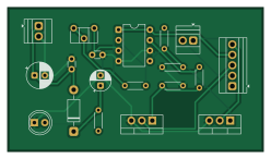
About the DC-to-AC-push pull inverter PCB
DC-to-AC-push pull inverter is an open source PCB design by MatthewSchaar, published on GitHub. It is a 2-layer board measuring 62 × 35 mm, with 19 components from 15 distinct parts.
Other key parts include the IR2153. By type, the board carries 6 resistors, 4 capacitors, 3 diodes, 2 transistors, 1 IC and 1 battery holder.
From the project
DC-to-AC push-pull inverter, 12 V to 240 V, designed from scratch in KiCad - schematic, PCB layout, a custom 3D model written in Python, and a full manufacturing file set.
A small push-pull inverter I create from scratch in KiCad - schematic, printed circuit board (PCB) layout, a custom 3D model written in Python, and a full manufacturing file set.
This is a design exercise. The PCB was never sent out to be fabricated; everything here lives in CAD.
A 12 V supply is switched back and forth through two MOSFETs into a transformer, which steps the voltage up to roughly 240 V AC. An IR2153 driver IC generates the switching on its own, with a trimmer to adjust how fast it runs.
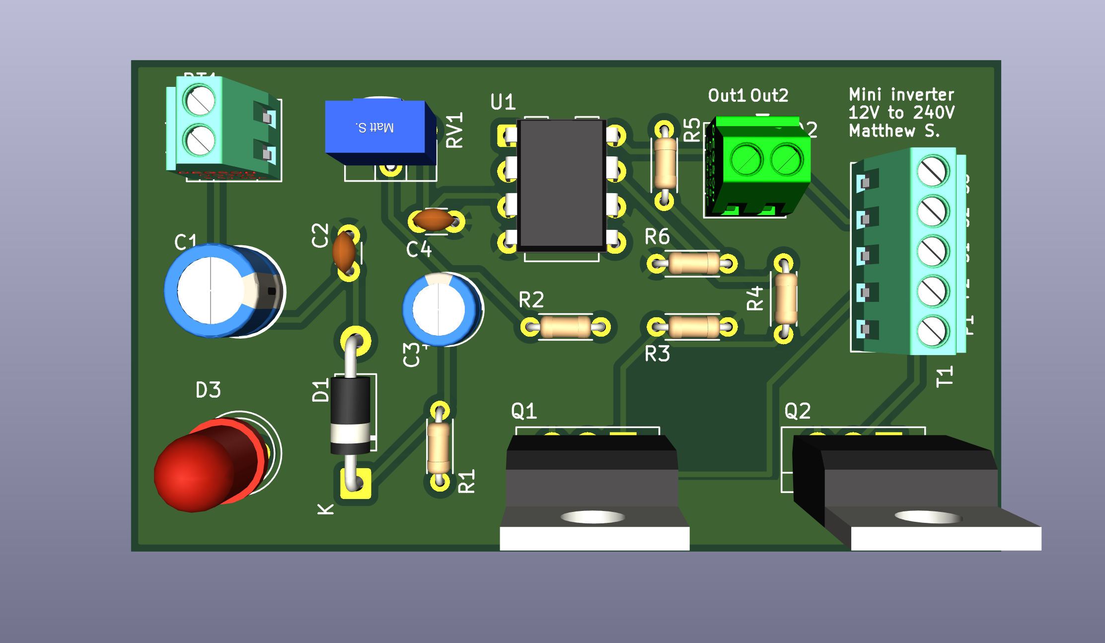
Main components on the DC-to-AC-push pull inverter
DC-to-AC-push pull inverter bill of materials (BOM)
19 components, 15 distinct parts.
| Qty | Part | Footprint | Refs |
|---|---|---|---|
| 1 | IR2153 | DIP-8_W7.62mm | U1 |
| 2 | IRLZ24 | TO-220-3_Vertical | Q1, Q2 |
| 1 | 12V | TerminalBlock_Xinya_XY308-2.54-2P_1x02_P2.54mm_Horizontal | BT1 |
| 1 | 10K | Potentiometer_ACP_CA6-H2,5_Horizontal | RV1 |
| 1 | Step Down 240V to 10-012V | TerminalBlock_Xinya_XY308-2.54-5P_1x05_P2.54mm_Horizontal | T1 |
| 1 | 1N4007 | D_DO-41_SOD81_P10.16mm_Horizontal | D1 |
| 1 | LED | TerminalBlock_Xinya_XY308-2.54-2P_1x02_P2.54mm_Horizontal | D2 |
| 1 | LED | LED_D5.0mm | D3 |
| 1 | 470uF | CP_Radial_D6.3mm_P2.50mm | C1 |
| 1 | 0.01uF | C_Disc_D3.0mm_W1.6mm_P2.50mm | C2 |
| 1 | 47uF | CP_Radial_D5.0mm_P2.50mm | C3 |
| 1 | 0.2uF | C_Disc_D3.0mm_W1.6mm_P2.50mm | C4 |
| 3 | 1K | R_Axial_DIN0204_L3.6mm_D1.6mm_P5.08mm_Horizontal | R1, R3, R6 |
| 1 | 22K | R_Axial_DIN0204_L3.6mm_D1.6mm_P5.08mm_Horizontal | R2 |
| 2 | 22R | R_Axial_DIN0204_L3.6mm_D1.6mm_P5.08mm_Horizontal | R4, R5 |
DC-to-AC-push pull inverter design files
The KiCad project lives in the MatthewSchaar/DC-to-AC-push-pull-inverter-PCB repository on GitHub; these links point at the commit this page was built from.
- LayoutMini_Inverter.kicad_pcb
- SchematicMini_Inverter.kicad_sch
DC-to-AC-push pull inverter: common questions
How big is the DC-to-AC-push pull inverter PCB?
The DC-to-AC-push pull inverter measures 62 × 35 mm, has 2 copper layers and is 1.6 mm thick.
How many components are on the DC-to-AC-push pull inverter?
19 components, from 15 distinct parts. The full bill of materials is listed on this page.
Where can I download the DC-to-AC-push pull inverter design files?
From the MatthewSchaar/DC-to-AC-push-pull-inverter-PCB repository on GitHub, which has the KiCad layout and the schematic; the links under Design files point to each one.
Can I use the DC-to-AC-push pull inverter design in my own project?
The repository has no license, so all rights stay with MatthewSchaar. Use it as a reference, and ask the author before reusing the design.