
Dimmer4

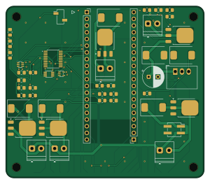
About the Dimmer4 PCB
Dimmer4 is an open source STM32 PCB design by Meo98, published on GitHub under the GPL-3.0 license. It is a 2-layer board measuring 75 × 65 mm, with 55 components from 36 distinct parts.
Its main chip is the C5456198, from the STM32 family. Other key parts include the C909765, C202238, C206109 and C7832. By type, the board carries 13 connectors, 7 capacitors, 7 resistors, 6 diodes, 5 ICs and 5 transistors.
It belongs with the robotics & motion designs in this gallery, and the repository also holds 2 earlier revisions of it.
From the project
Stackable, contract-driven module system for the Raspberry Pi Pico — open hardware, built by code
One board plus a Pico is a working device. PicoStack v2 abolishes the separate base board that v1 needed: every 75 × 65 mm module now carries its own 6–30 V supply (reverse-polarity protection, TVS, a K7805-1000R3 regulator, Schottky-OR into VSYS) and a pair of Pico-native 1×20 socket rows (17.78 mm apart, the Pico's own pinout) — the Pico plugs straight into the top of the stack and all 40 pins run down through it. Stack several fed boards and they coexist; one is enough to power the whole chain. Every module also breaks out its 18 spare Pico GPIOs plus 3V3/GND as labelled solder pads on the…
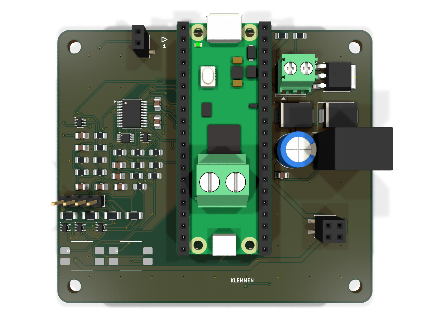
Main components on the Dimmer4
Dimmer4 bill of materials (BOM)
55 components, 36 distinct parts — part numbers from the project's BOM.
| Qty | Part | Footprint | Refs |
|---|---|---|---|
| 1 | C909765 K7805-1000R3 | Converter_DCDC_RECOM_R-78B-2.0_THT | U90 |
| 1 | C5456198 STM32C011F6P6 | TSSOP-20_4.4x6.5mm_P0.65mm | U100 |
| 1 | C202238 SN74LVC1G175 | SOT-363_SC-70-6 | U101 |
| 1 | C206109 SN74LVC2G00DCUR | VSSOP-8_2.3x2mm_P0.5mm | U102 |
| 1 | C7832 SN74LVC1G08 | SOT-353_SC-70-5 | U103 |
| 4 | NCE6020AK | TO-252-3_TabPin2 | Q1, Q2, Q3, Q4 |
| 1 | C2624 IRFR5305 | TO-252-3_TabPin2 | Q90 |
| 1 | C395868 LED-Kanal 1 | TerminalBlock_Phoenix_PT-1,5-2-3.5-H_1x02_P3.50mm_Horizontal | J5 |
| 1 | LED-Kanal 2 | TerminalBlock_Phoenix_PT-1,5-2-3.5-H_1x02_P3.50mm_Horizontal | J6 |
| 1 | LED-Kanal 3 | TerminalBlock_Phoenix_PT-1,5-2-3.5-H_1x02_P3.50mm_Horizontal | J7 |
| 1 | LED-Kanal 4 | TerminalBlock_Phoenix_PT-1,5-2-3.5-H_1x02_P3.50mm_Horizontal | J8 |
| 1 | C474892 Versorgung Eingang | TerminalBlock_Phoenix_PT-1,5-2-3.5-H_1x02_P3.50mm_Horizontal | J90 |
| 1 | Randpads GPIO, unbestueckt (THT-Loetpad) | Randpad_Reihe_1x18 | J95 |
| 1 | Randpads Versorgung: 2x 3V3 + 2x GND, unbestueckt (THT-Loetpad) | Randpad_Reihe_1x04 | J96 |
| 1 | Stapelstecker links, Pico-Pins 1..20 (Buchse) | PinSocket_1x20_P2.54mm_Vertical | J100 |
| 1 | Kettenstecker, Buchse oben (SMD) | PinSocket_1x02_P2.54mm_Vertical_SMD_Pin1Left | J101 |
| 1 | Kettenstecker, Stift unten (SMD) | PinHeader_1x02_P2.54mm_Vertical_SMD_Pin1Left | J102 |
| 1 | Leistungsstecker, Buchse oben (SMD) | PinSocket_2x02_P2.54mm_Vertical_SMD | J103 |
| 1 | Leistungsstecker, Stift unten (SMD) | PinHeader_2x02_P2.54mm_Vertical_SMD | J104 |
| 1 | Stapelstecker rechts, Pico-Pins 21..40 (Buchse) | PinSocket_1x20_P2.54mm_Vertical | J105 |
Show 16 more
| Qty | Part | Footprint | Refs |
|---|---|---|---|
| 4 | M3 | H1, H2, H3, H4 | |
| 4 | 100 | R_0805_2012Metric_Pad1.20x1.40mm_HandSolder | RG1, RG2, RG3, RG4 |
| 4 | 100k | R_0805_2012Metric_Pad1.20x1.40mm_HandSolder | RP1, RP2, RP3, RP4 |
| 4 | SS36C | D_SMC | D1, D2, D3, D4 |
| 1 | C340696 SMCJ30A | D_SMC | D90 |
| 1 | C16237 SS36C | D_SMC | D91 |
| 1 | C45078 220u | CP_Radial_D8.0mm_P3.50mm | C90 |
| 1 | C45783 22u | C_0805_2012Metric_Pad1.18x1.45mm_HandSolder | C91 |
| 1 | C49678 100n | C_0805_2012Metric_Pad1.18x1.45mm_HandSolder | C100 |
| 1 | C28323 1000n | C_0805_2012Metric_Pad1.18x1.45mm_HandSolder | C101 |
| 3 | 100n | C_0805_2012Metric_Pad1.18x1.45mm_HandSolder | C102, C103, C104 |
| 2 | C17414 10k | R_0805_2012Metric_Pad1.20x1.40mm_HandSolder | R90, R91 |
| 1 | C17798 Kennwiderstand (Modultyp) | R_0805_2012Metric_Pad1.20x1.40mm_HandSolder | R100 |
| 1 | C17477 Kennwiderstand (Modultyp) | R_0805_2012Metric_Pad1.20x1.40mm_HandSolder | R101 |
| 1 | C149504 100k | R_0805_2012Metric_Pad1.20x1.40mm_HandSolder | R102 |
| 2 | C17414 10000 (ID_OBEN) | R_0805_2012Metric_Pad1.20x1.40mm_HandSolder | R104, R105 |
Dimmer4 design files
The KiCad project lives in the Meo98/picostack repository on GitHub; these links point at the commit this page was built from.
Dimmer4: common questions
What microcontroller does the Dimmer4 use?
The Dimmer4 is built around the C5456198, from the STM32 family.
How big is the Dimmer4 PCB?
The Dimmer4 measures 75 × 65 mm, has 2 copper layers and is 1.6 mm thick.
How many components are on the Dimmer4?
55 components, from 36 distinct parts, with part numbers taken from the project's own BOM. The full bill of materials is listed on this page.
Where can I download the Dimmer4 design files?
From the Meo98/picostack repository on GitHub, which has the KiCad layout, the schematic and the BOM; the links under Design files point to each one.
Can I use the Dimmer4 design in my own project?
Yes, under the terms of its GPL-3.0 license, which Meo98 chose for the repository.
Can I test firmware for the Dimmer4 without the hardware?
Yes. HardLabs builds a simulation of the board from its netlist and BOM, so you can run and debug STM32 firmware against it before you order a PCB.
More boards in picostack
Earlier revisions in the repo: Dimmer3, Dimmer1
Similar boards
 STM32
STM32AxxSolder
AxxAxx
39 × 82.5 mm122 parts2LGPL-3.01.7k STM32
STM32AIOC
skuep
21 × 31.5 mm47 parts2LMIT1.4k STM32
STM32Ferris
pierrechevalier83
208.8 × 86.8 mm102 parts2LSHL-2.11.3k STM32
STM32Module 16S
stuartpittaway
71.1 × 89.6 mm113 parts4LCC-BY-NC-4.01.1k STM32
STM32Djinn
tzarc
192.3 × 150.5 mm216 parts2LCERN-OHL-S-2.0988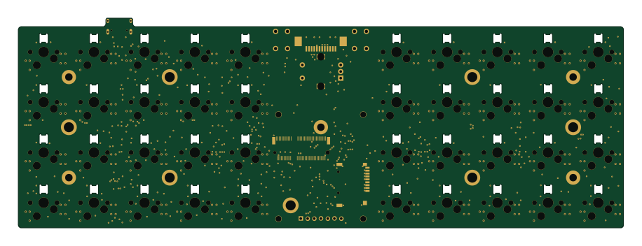 STM32
STM32Ghoul
228.6 × 79.4 mm163 parts2LCERN-OHL-S-2.0988