
Embedded Elevator Control Prototype

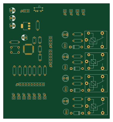
About the Embedded Elevator Control Prototype PCB
Embedded Elevator Control Prototype is an open source STM32 PCB design by mhafezan, published on GitHub under the MIT license. It is a 2-layer board measuring 94.2 × 102 mm, with 60 components from 28 distinct parts.
Its main chip is the STM32F103C8T6, from the STM32 family. Other key parts include the AMS1117-3.3. By type, the board carries 17 resistors, 15 connectors, 8 capacitors, 4 transistors, 4 relays and 4 LEDs.
From the project
This project implements a simplified embedded elevator controller firmware in C, demonstrating FSM-based control logic, FIFO floor-request handling, motor command generation, and safety mechanisms such as emergency stop, door obstruction, and limit-switch protection. It provides both terminal-based and GUI-based simulation environment.
A C-based embedded elevator controller prototype that simulates the core logic of a multi-floor elevator system using a finite-state machine. The project includes both a terminal-based simulator and a graphical simulator built with raylib.
This project demonstrates embedded control concepts such as state-machine design, safety input handling, request queue management, motor control logic, and separation between controller firmware logic and user-interface visualization.
Main components on the Embedded Elevator Control Prototype
Embedded Elevator Control Prototype bill of materials (BOM)
60 components, 28 distinct parts.
| Qty | Part | Footprint | Refs |
|---|---|---|---|
| 1 | STM32F103C8T6 | LQFP-48_7x7mm_P0.5mm | U1 |
| 1 | AMS1117-3.3 | SOT-223-3_TabPin2 | U2 |
| 4 | 2N2222 | TO-92_Inline | Q1, Q2, Q3, Q4 |
| 1 | Power Input | PinHeader_1x03_P2.54mm_Vertical | J1 |
| 1 | MCU Input Header | PinHeader_1x10_P2.54mm_Vertical | J2 |
| 1 | Floor 1 Button | PinHeader_1x02_P2.54mm_Vertical | J3 |
| 1 | Floor 2 Button | PinHeader_1x02_P2.54mm_Vertical | J4 |
| 1 | Floor 3 Button | PinHeader_1x02_P2.54mm_Vertical | J5 |
| 1 | Door Sensor | PinHeader_1x02_P2.54mm_Vertical | J6 |
| 1 | Emergency Stop | PinHeader_1x02_P2.54mm_Vertical | J7 |
| 1 | Upper Limit Switch | PinHeader_1x02_P2.54mm_Vertical | J8 |
| 1 | Lower Limit Switch | PinHeader_1x02_P2.54mm_Vertical | J9 |
| 1 | MCU Output Header | PinHeader_1x06_P2.54mm_Vertical | J10 |
| 1 | Motor UP Output | PinHeader_1x02_P2.54mm_Vertical | J11 |
| 1 | Motor DOWN Output | PinHeader_1x02_P2.54mm_Vertical | J12 |
| 1 | Door OPEN Output | PinHeader_1x02_P2.54mm_Vertical | J13 |
| 1 | Door CLOSE Output | PinHeader_1x02_P2.54mm_Vertical | J14 |
| 1 | SWD_IO | PinHeader_1x04_P2.54mm_Vertical | J15 |
| 4 | Relay_SPDT | Relay_SPDT_SANYOU_SRD_Series_Form_C | K1, K2, K3, K4 |
| 1 | SW_Push | SW_PUSH_6mm | SW1 |
Show 8 more
| Qty | Part | Footprint | Refs |
|---|---|---|---|
| 1 | SW_SPDT | SW_SPDT_PCM12 | SW2 |
| 4 | Status_LED | LED_D5.0mm | LED1, LED2, LED3, LED4 |
| 4 | 1N4007 | D_DO-41_SOD81_P10.16mm_Horizontal | D1, D2, D3, D4 |
| 4 | 10uF | CP_Radial_D5.0mm_P2.50mm | C2, C3, C4, C5 |
| 4 | 100nF | C_Disc_D5.0mm_W2.5mm_P5.00mm | C6, C7, C8, C9 |
| 9 | 10k | R_Axial_DIN0207_L6.3mm_D2.5mm_P7.62mm_Horizontal | R1, R2, R3, R4, R5, R6, R7, R16 +1 |
| 4 | 1k | R_Axial_DIN0207_L6.3mm_D2.5mm_P7.62mm_Horizontal | R8, R9, R10, R11 |
| 4 | 330 | R_Axial_DIN0207_L6.3mm_D2.5mm_P7.62mm_Horizontal | R12, R13, R14, R15 |
Embedded Elevator Control Prototype design files
The KiCad project lives in the mhafezan/Embedded_Elevator_Control_Prototype repository on GitHub; these links point at the commit this page was built from.
Embedded Elevator Control Prototype: common questions
What microcontroller does the Embedded Elevator Control Prototype use?
The Embedded Elevator Control Prototype is built around the STM32F103C8T6, from the STM32 family.
How big is the Embedded Elevator Control Prototype PCB?
The Embedded Elevator Control Prototype measures 94.2 × 102 mm, has 2 copper layers and is 1.6 mm thick.
How many components are on the Embedded Elevator Control Prototype?
60 components, from 28 distinct parts. The full bill of materials is listed on this page.
Where can I download the Embedded Elevator Control Prototype design files?
From the mhafezan/Embedded_Elevator_Control_Prototype repository on GitHub, which has the KiCad layout and the schematic; the links under Design files point to each one.
Can I use the Embedded Elevator Control Prototype design in my own project?
Yes, under the terms of its MIT license, which mhafezan chose for the repository.
Can I test firmware for the Embedded Elevator Control Prototype without the hardware?
Yes. HardLabs builds a simulation of the board from its netlist and BOM, so you can run and debug STM32 firmware against it before you order a PCB.
Similar boards
 STM32
LumenPnP Motherboard
opulo-inc
149 × 95 mm296 parts4LCC-BY-SA-4.03.7k STM32
Type g
google
169 × 30 mm24 parts2LApache-2.02.9k STM32
Main panel
234 × 84 mm26 parts4LApache-2.02.9k STM32
Base
52.3 × 52.3 mm36 parts2LApache-2.02.9k STM32
Type a
150 × 30 mm14 parts2LApache-2.02.9k STM32
Type c
188 × 30 mm17 parts2LApache-2.02.9k