
OpenRZ67 trigger, nRF52 / coin cell

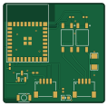
About the OpenRZ67 trigger, nRF52 / coin cell PCB
OpenRZ67 trigger, nRF52 / coin cell is an open source PCB design by mhellevang, published on GitHub under the MIT license. It is a 2-layer board measuring 29.5 × 29 mm, with 15 components from 12 distinct parts.
Other key parts include the E73-2G4M08S1F and TLP172AM(TPL,E). By type, the board carries 3 ICs, 3 capacitors, 3 resistors, 2 connectors, 1 transistor and 1 battery holder.
It belongs with the iot & wireless designs in this gallery.
From the project
Bluetooth remote release for the Mamiya RZ67: ESP32-C3 firmware, KiCad PCB and enclosure. Shutter, bulb and countdown from your phone.
KiCad 10 project for the coin-cell trigger: 29.5 × 29 mm, 2 layers, Ebyte E73-2G4M08S1F (nRF54L15) module, CR2032 clip on the back, two TLP172AM PhotoMOS relays, JST SH 1.0 mm side-entry camera connector, a second SH connector for SWD, one button, one LED, a P-MOSFET against a reversed cell. No regulator, no charger, no power switch. Concept stage, not fabricated.
Main components on the OpenRZ67 trigger, nRF52 / coin cell
OpenRZ67 trigger, nRF52 / coin cell bill of materials (BOM)
15 components, 12 distinct parts — part numbers from the project's BOM.
| Qty | Part | Footprint | Refs |
|---|---|---|---|
| 1 | E73-2G4M08S1F Ebyte | WIRELM-SMD_E73-2G4M08S1F | U1 |
| 2 | TLP172AM(TPL,E) TLP172AM TOSHIBA | SMD-4_L4.6-W3.7-P2.54-LS7.0-BR | U2, U3 |
| 1 | AO3401A Alpha & Omega Semicon | SOT-23 | Q1 |
| 1 | SM04B-SRSS-TB(LF)(SN) Camera JST | CONN-SMD_4P-P1.00_SM04B-SRSS-TB-LF-SN | J1 |
| 1 | SM04B-SRSS-TB(LF)(SN) SWD JST | CONN-SMD_4P-P1.00_SM04B-SRSS-TB-LF-SN | J2 |
| 1 | MY-2032-16 CR2032 MYOUNG | BAT-SMD_MY-2032-16 | BT1 |
| 1 | B3U-1000P OMRON | KEY-SMD_B3U-1000PM | SW1 |
| 1 | KT-0603R LED KENTO | LED0603-RD | D1 |
| 1 | CL31A107MQHNNNE 100uF Samsung | C1206 | C1 |
| 2 | CL05B104KO5NNNC 100nF Samsung | C0402 | C2, C3 |
| 2 | 0402WGF2200TCE 220Ω UNI-ROYAL | R0402 | R1, R2 |
| 1 | 0402WGF1001TCE 1kΩ UNI-ROYAL | R0402 | R3 |
OpenRZ67 trigger, nRF52 / coin cell design files
The KiCad project lives in the mhellevang/openrz67-trigger repository on GitHub; these links point at the commit this page was built from.
OpenRZ67 trigger, nRF52 / coin cell: common questions
How big is the OpenRZ67 trigger, nRF52 / coin cell PCB?
The OpenRZ67 trigger, nRF52 / coin cell measures 29.5 × 29 mm, has 2 copper layers and is 1.6 mm thick.
How many components are on the OpenRZ67 trigger, nRF52 / coin cell?
15 components, from 12 distinct parts, with part numbers taken from the project's own BOM. The full bill of materials is listed on this page.
Where can I download the OpenRZ67 trigger, nRF52 / coin cell design files?
From the mhellevang/openrz67-trigger repository on GitHub, which has the KiCad layout, the schematic and the BOM; the links under Design files point to each one.
Can I use the OpenRZ67 trigger, nRF52 / coin cell design in my own project?
Yes, under the terms of its MIT license, which mhellevang chose for the repository.
More boards in openrz67-trigger
Similar boards

EinkPDA screen
TalismanDesign
95 × 54 mm27 parts2LApache-2.02.0k
RPi RM0 WiFi/Bluetooth Module
schlae
11.1 × 14 mm76 parts6LNo license1.0k
L0 USB
Luos-io
20.3 × 15.3 mm19 parts2LMIT547
Breakout board
26.7 × 27.9 mm29 parts2LMIT547
Stm32f0 disco Luos shield
55.9 × 99.1 mm26 parts2LMIT547
L0 USBA
20.3 × 15.3 mm19 parts2LMIT547