
OpenRZ67 camera trigger

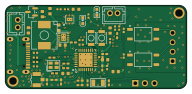
About the OpenRZ67 camera trigger PCB
OpenRZ67 camera trigger is an open source ESP32 PCB design by mhellevang, published on GitHub under the MIT license. It is a 2-layer board measuring 48 × 22 mm, with 59 components from 34 distinct parts.
Its main chip is the ESP32-C3FH4, from the ESP32 family. Other key parts include the TPS63031DSKR, BQ25185DLHR, C157925, TLP172AM and C88374. By type, the board carries 22 capacitors, 17 resistors, 6 ICs, 3 switches, 3 inductors and 2 crystals.
It belongs with the iot & wireless and power & battery designs in this gallery.
From the project
Bluetooth remote release for the Mamiya RZ67: ESP32-C3 firmware, KiCad PCB and enclosure. Shutter, bulb and countdown from your phone.
KiCad 10 project for the OpenRZ67 trigger board: 48 × 22 mm, 2 layers, ESP32-C3, two TLP172AM PhotoMOS relays, BQ25185 charger + TPS63031 buck-boost. This is the source. Each fabricated revision's upload package is frozen in ../archive/, and the EasyEDA Pro project it was ported from in ../archive/easyeda/.
Everything in out/ is generated. Rebuild all of it with one command, so the committed outputs and the check reports always describe the committed sources:
Main components on the OpenRZ67 camera trigger
OpenRZ67 camera trigger bill of materials (BOM)
59 components, 34 distinct parts — part numbers from the project's BOM.
| Qty | Part | Footprint | Refs |
|---|---|---|---|
| 1 | ESP32-C3FH4 ESPRESSIF(乐鑫) | QFN-32_L5.0-W5.0-P0.50-BL-EP3.7 | U1 |
| 1 | TPS63031DSKR Texas Instruments | VSON-10_L2.5-W2.5-P0.50-EP1.2x2.0 | U2 |
| 1 | BQ25185DLHR Texas Instruments | WSON-10_L2.2-W2.0-P0.40-EP0.9x1.5 | U3 |
| 1 | C157925 S4B-XH-A(LF)(SN) JST | CONN-TH_S4B-XH-A-LF-SN | U4 |
| 2 | TLP172AM TOSHIBA(东芝) | SMD-4_L4.6-W3.7-P2.54-LS7.0-BR | U5, U6 |
| 1 | C88374 U.FL-R-SMT-1(80) HRS(广濑) | RF-SMD_FRF05002-JSS103M | A1 |
| 1 | AO3401A Alpha & Omega Semicon | SOT-23 | Q3 |
| 1 | T201640MFBDE2X 40MHz YJX(雅晶鑫) | CRYSTAL-SMD_4P-L2.0-W1.6-BL-2 | X1 |
| 1 | XKXGI-SUA-32.768K 32.768kHz YXC(扬兴晶振) | CRYSTAL-SMD_L3.2-W1.5-1 | X2 |
| 1 | C131337 B2B-PH-K-S(LF)(SN) JST | CONN-TH_B2B-PH-K-S | BAT1 |
| 2 | B3U-1000P OMRON(欧姆龙) | KEY-SMD_B3U-1000PM | S1, S2 |
| 1 | C131337 B2B-PH-K-S(LF)(SN) JST | CONN-TH_B2B-PH-K-S | S3 |
| 1 | C2765186 TYPE-C 16PIN 2MD(073) SHOU HAN(首韩) | USB-C-SMD_TYPE-C-6PIN-2MD-073 | USB1 |
| 1 | KT-0603R KENTO | LED0603-RD | D3 |
| 1 | XL-1608UBC-04 XINGLIGHT(成兴光) | LED0603-RD_BLUE | D4 |
| 1 | LQG15HS3N9S02D 3.9nH muRata(村田) | L0402 | L1 |
| 1 | BLM15AG601SN1D muRata(村田) | L0402 | L2 |
| 1 | SPM6530T-2R2M 2.2uH TDK | IND-SMD_L7.1-W6.5-P5.60 | L3 |
| 2 | CC0402CRNPO9BN1R0 1pF YAGEO(国巨) | C0402 | C1, C2 |
| 7 | GRM155R71H104KE14D 100nF muRata(村田) | C0402 | C3, C4, C5, C6, C7, C25, C32 |
Show 14 more
| Qty | Part | Footprint | Refs |
|---|---|---|---|
| 2 | GJM1555C1H150FB01D 15pF muRata(村田) | C0402 | C8, C9 |
| 3 | CL10A105KB8NNNC 1uF Samsung Electro-Mechanics | C0603 | C14, C26, C29 |
| 6 | CL10A106MA8NRNC 10uF SAMSUNG(三星) | C0603 | C15, C20, C21, C22, C23, C24 |
| 2 | GRM1555C1H180FA01D 18pF muRata(村田) | C0402 | C30, C31 |
| 2 | 0402WGF220JTCE 22Ω UNI-ROYAL(厚声) | R0402 | R4, R5 |
| 4 | 0402WGF1002TCE 10kΩ UNI-ROYAL(厚声) | R0402 | R6, R7, R8, R23 |
| 2 | 0402WGF5101TCE 5.1kΩ UNI-ROYAL(厚声) | R0402 | R9, R10 |
| 1 | 0402WGF2701TCE 2.7kΩ UNI-ROYAL(厚声) | R0402 | R11 |
| 1 | 0402WGF1802TCE 18kΩ UNI-ROYAL(厚声) | R0402 | R13 |
| 1 | NCP18XH103F03RB muRata(村田) | R0603 | R16 |
| 1 | FRC0402F3001TS 3kΩ FOJAN | R0402 | R18 |
| 1 | 0402WGF1001TCE 1kΩ UNI-ROYAL(厚声) | R0402 | R20 |
| 2 | 0402WGF1500TCE 150Ω UNI-ROYAL(厚声) | R0402 | R21, R22 |
| 2 | 0402WGF1004TCE 1MΩ UNI-ROYAL(厚声) | R0402 | R24, R25 |
OpenRZ67 camera trigger design files
The KiCad project lives in the mhellevang/openrz67-trigger repository on GitHub; these links point at the commit this page was built from.
OpenRZ67 camera trigger: common questions
What microcontroller does the OpenRZ67 camera trigger use?
The OpenRZ67 camera trigger is built around the ESP32-C3FH4, from the ESP32 family.
How big is the OpenRZ67 camera trigger PCB?
The OpenRZ67 camera trigger measures 48 × 22 mm, has 2 copper layers and is 1.6 mm thick.
How many components are on the OpenRZ67 camera trigger?
59 components, from 34 distinct parts, with part numbers taken from the project's own BOM. The full bill of materials is listed on this page.
Where can I download the OpenRZ67 camera trigger design files?
From the mhellevang/openrz67-trigger repository on GitHub, which has the KiCad layout, the schematic and the BOM; the links under Design files point to each one.
Can I use the OpenRZ67 camera trigger design in my own project?
Yes, under the terms of its MIT license, which mhellevang chose for the repository.
Can I test firmware for the OpenRZ67 camera trigger without the hardware?
Yes. HardLabs builds a simulation of the board from its netlist and BOM, so you can run and debug ESP32 firmware against it before you order a PCB.
More boards in openrz67-trigger
Similar boards
 ESP32
OSO-BOOK-B1
joeycastillo
85 × 115 mm65 parts2LCC-BY-SA-4.08.1k ESP32
Powertrain
byrantech
64 × 45.4 mm171 parts4LMIT4.3k ESP32
Badge
atopile
56.3 × 39 mm239 parts4LMIT4.0k ESP32
Esp32 minimal
36.2 × 26.8 mm20 parts2LMIT4.0k ESP32
Controller
StuckAtPrototype
29 × 74 mm58 parts4LApache-2.03.8k ESP32
Racer
36 × 50.2 mm70 parts4LApache-2.03.8k