
Pcb pwm board

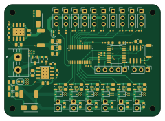
About the Pcb pwm board
Pcb pwm board is an open source STM32 PCB design by Mich-Dich, published on GitHub under the MIT license. It is a 4-layer board measuring 60 × 43 mm, with 91 components from 31 distinct parts.
Its main chip is the STM32L010F4P6, from the STM32 family. Other key parts include the SP3485EN, TPS5430DDA and PCA9635PW,118. By type, the board carries 27 resistors, 20 capacitors, 19 connectors, 10 diodes, 7 transistors and 5 ICs.
It belongs with the robotics & motion designs in this gallery.
From the project
A PCB created with KiCad whats provides 10 servo outputs and 6 general purpose 12V outputs. It communicates via RS-485
The PWM Board is a 16‑channel PWM controller board designed for driving servos, LEDs, or small DC motors. It is built around the PCA9685 16‑channel 12‑bit PWM driver, controlled by an STM32L010F4P6 Arm® Cortex®‑M0+ MCU. Communication is via RS‑485 (using a SP3485 transceiver), making it suitable for remote or industrial applications. The board also features six low‑side N‑MOSFET outputs (with flyback diodes) for higher‑current loads such as motors or solenoids, and a dedicated 3.3 V buck converter (SY81051) that generates the logic supply from a 12 V input.
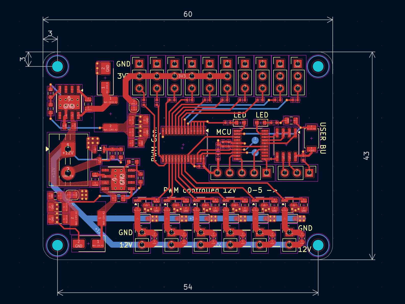
Main components on the Pcb pwm board
Pcb pwm board bill of materials (BOM)
91 components, 31 distinct parts.
| Qty | Part | Footprint | Refs |
|---|---|---|---|
| 1 | STM32L010F4P6 | TSSOP-20_4.4x6.5mm_P0.65mm | U1 |
| 1 | SP3485EN | SOIC-8_3.9x4.9mm_P1.27mm | U2 |
| 2 | TPS5430DDA | TI_SO-PowerPAD-8_ThermalVias | U3, U6 |
| 1 | PCA9635PW,118 | TSSOP-28_4.4x9.7mm_P0.65mm | U5 |
| 6 | Q_NMOS | SOT-23 | Q0, Q1, Q2, Q3, Q4, Q5 |
| 1 | Q_NMOS | SOT-23-3 | Q7 |
| 10 | Conn_01x03_Pin | PinHeader_1x03_P2.54mm_Vertical | J0, J1, J2, J3, J4, J5, J6, J7 +2 |
| 1 | SWD_CONN | PinHeader_1x05_P2.54mm_Vertical | J11 |
| 6 | Conn_01x02_Pin | PinHeader_1x02_P2.54mm_Vertical | J12, J13, J14, J15, J16, J17 |
| 1 | Communiation_IN | PinHeader_1x03_P2.54mm_Vertical | J18 |
| 1 | Power_IN | TerminalBlock_MaiXu_MX126-5.0-02P_1x02_P5.00mm | J19 |
| 1 | USER_SW | SW_PUSH_TS-1088-AR02016 | SW1 |
| 2 | SS34 | D_SMA | D1, D10 |
| 1 | RED | LED_0603_1608Metric | D2 |
| 1 | GREEN | LED_0603_1608Metric | D3 |
| 6 | D | D_SOD-323 | D4, D5, D6, D7, D8, D9 |
| 2 | 15u | CYA0630 | L1, L2 |
| 2 | 100n | C_0402_1005Metric | C1, C4 |
| 6 | 10u | C_0603_1608Metric | C2, C5, C6, C7, C14, C15 |
| 2 | 10u | C_0402_1005Metric | C3, C21 |
Show 11 more
| Qty | Part | Footprint | Refs |
|---|---|---|---|
| 4 | 100u | C_1206_3216Metric | C8, C9, C18, C19 |
| 2 | 22u | C_0805_2012Metric | C10, C20 |
| 2 | 10u | C_0805_2012Metric | C11, C16 |
| 2 | 10n | C_0805_2012Metric | C12, C17 |
| 7 | 10K | R_0805_2012Metric | R1, R22, R23, R24, R25, R26, R27 |
| 2 | 1K5 | R_0402_1005Metric | R3, R4 |
| 2 | 12k | R_0603_1608Metric | R5, R9 |
| 2 | 6K8 | R_0603_1608Metric | R6, R28 |
| 2 | 51k | R_0603_1608Metric | R7, R8 |
| 10 | 220 | R_0402_1005Metric | R10, R11, R12, R13, R14, R15, R16, R17 +2 |
| 2 | 4K7 | R_0402_1005Metric | R20, R21 |
Pcb pwm board design files
The KiCad project lives in the Mich-Dich/pcb_pwm_board repository on GitHub; these links point at the commit this page was built from.
- Layoutki_cad/pwm_board.kicad_pcb
- Schematicki_cad/pwm_board.kicad_sch
Pcb pwm board: common questions
What microcontroller does the Pcb pwm board use?
The Pcb pwm board is built around the STM32L010F4P6, from the STM32 family.
How big is the Pcb pwm board?
The Pcb pwm board measures 60 × 43 mm, has 4 copper layers and is 1.6 mm thick.
How many components are on the Pcb pwm board?
91 components, from 31 distinct parts. The full bill of materials is listed on this page.
Where can I download the Pcb pwm board design files?
From the Mich-Dich/pcb_pwm_board repository on GitHub, which has the KiCad layout and the schematic; the links under Design files point to each one.
Can I use the Pcb pwm board design in my own project?
Yes, under the terms of its MIT license, which Mich-Dich chose for the repository.
Can I test firmware for the Pcb pwm board without the hardware?
Yes. HardLabs builds a simulation of the board from its netlist and BOM, so you can run and debug STM32 firmware against it before you order a PCB.
Similar boards
 STM32
STM32LumenPnP Motherboard
opulo-inc
149 × 95 mm296 parts4LCC-BY-SA-4.03.7k STM32
STM32Type c
google
188 × 30 mm17 parts2LApache-2.02.9k STM32
STM32Main panel
234 × 84 mm26 parts4LApache-2.02.9k STM32
STM32Base
52.3 × 52.3 mm36 parts2LApache-2.02.9k STM32
STM32Type a
150 × 30 mm14 parts2LApache-2.02.9k STM32
STM32Type e
140.5 × 30 mm13 parts2LApache-2.02.9k