
LED-Relay

About the LED-Relay PCB
LED-Relay is an open source AVR/Arduino PCB design by mikelawrence, published on GitHub under the MIT license. It is a 2-layer board measuring 38.1 × 19.1 mm, with 45 components from 20 distinct parts.
Its main chip is the ATXMEGA8E5-M4U, from the AVR/Arduino family. Other key parts include the LT3014IDD and BTS70082EPAXUMA1. By type, the board carries 13 resistors, 12 capacitors, 9 connectors, 4 diodes, 3 ICs and 3 test points.
From the project
Motorcycle LED Relay replacement PCB.
There are 4 inputs to the LED Relay board: +12V - This should be connected through a fuse to the battery and should remain hot even when the trike is off. All power to the outputs comes from this wire. ACC1 - This is +12V when the bike is turned on (ignition). ACC2 - This is +12V when the LED lights should be on. GND - Chassis and negative terminal of the battery. The current software turns both outputs on when both ACC1 and ACC2 are at +12V but this can easily be changed to two independent outputs each controlled by its own ACC input. When either ACC1 off the micro-controller enters a low…
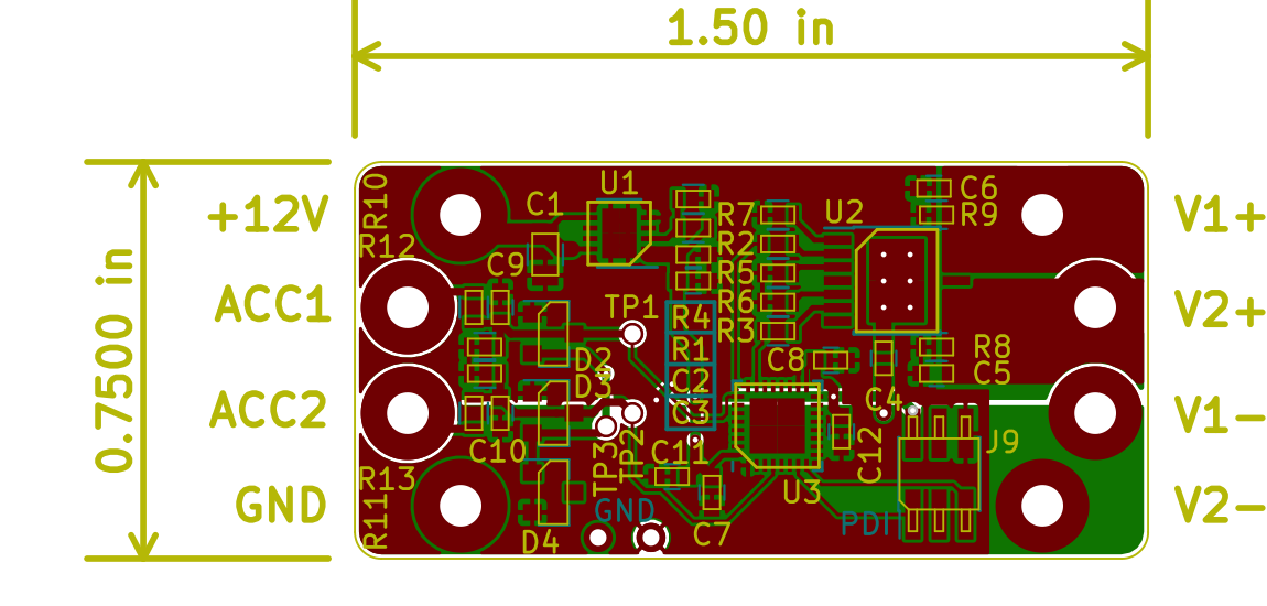
Main components on the LED-Relay
LED-Relay bill of materials (BOM)
45 components, 20 distinct parts — part numbers from the project's BOM.
| Qty | Part | Footprint | Refs |
|---|---|---|---|
| 1 | LT3014IDD Linear Tech | DFN-8-1EP_3x3mm_Pitch0.5mm | U1 |
| 1 | BTS70082EPAXUMA1 BTS7008-2EPA Infineon | Infineon_PG-TSDSO-14-22 | U2 |
| 1 | ATXMEGA8E5-M4U Atmel | QFN-32-1EP_4x4mm_Pitch0.4mm | U3 |
| 8 | TEST_1P | SolderWirePad_single_2mmDrill | J1, J2, J3, J4, J5, J6, J7, J8 |
| 1 | 20021121-00006C4LF Header Amphenol/FCi | Pin_Header_Straight_2x03_Pitch1.27mm_SMD | J9 |
| 1 | GND | WireConnection_0.80mmDrill_ThinPad | JP1 |
| 3 | TEST_1P | SolderWirePad_single_0-8mmDrill | TP1, TP2, TP3 |
| 1 | SM15T33CA ST | D_SMC_Handsoldering | D1 |
| 2 | BAT54S Nexperia | SOT-23 | D2, D3 |
| 1 | ZRC330F01TA ZRC330 Diodes Inc. | SOT-23 | D4 |
| 1 | GRJ21BC72A105KE11L 1uF Murata Electronics | C_0805 | C1 |
| 4 | 0.47uF | C_0603 | C2, C3, C7, C8 |
| 1 | GCJ188R92A683KA01D 68nF Murata Electronics | C_0603 | C4 |
| 6 | 10nF | C_0603 | C5, C6, C9, C10, C11, C12 |
| 1 | CRCW06032M15FKEA 2.15M Vishay | R_0603 | R1 |
| 2 | RC0603JR-074K7L 4.7k Yageo | R_0603 | R2, R3 |
| 1 | CRCW06031M27FKEA 1.27M Vishay | R_0603 | R4 |
| 2 | RC0603JR-0710KL 10k Yageo | R_0603 | R5, R6 |
| 1 | RC0603FR-0747RL 47 Yageo | R_0603 | R7 |
| 6 | 47k | R_0603 | R8, R9, R10, R11, R12, R13 |
LED-Relay design files
The KiCad project lives in the mikelawrence/LED-Relay repository on GitHub; these links point at the commit this page was built from.
- LayoutLED Relay.kicad_pcb
- BOMLED Relay-BOM.csv
LED-Relay: common questions
What microcontroller does the LED-Relay use?
The LED-Relay is built around the ATXMEGA8E5-M4U, from the AVR/Arduino family.
How big is the LED-Relay PCB?
The LED-Relay measures 38.1 × 19.1 mm, has 2 copper layers and is 1.6 mm thick.
How many components are on the LED-Relay?
45 components, from 20 distinct parts, with part numbers taken from the project's own BOM. The full bill of materials is listed on this page.
Where can I download the LED-Relay design files?
From the mikelawrence/LED-Relay repository on GitHub, which has the KiCad layout and the BOM; the links under Design files point to each one.
Can I use the LED-Relay design in my own project?
Yes, under the terms of its MIT license, which mikelawrence chose for the repository.
Can I test firmware for the LED-Relay without the hardware?
Yes. HardLabs builds a simulation of the board from its netlist and BOM, so you can run and debug AVR/Arduino firmware against it before you order a PCB.
Similar boards
 AVR/Arduino
Redox keyboard
mattdibi
162.2 × 126.5 mm77 parts2LMIT2.0k AVR/Arduino
ModuleV450
stuartpittaway
30 × 61.4 mm39 parts2LCC-BY-NC-4.01.1k AVR/Arduino
V4
30 × 50 mm38 parts2LCC-BY-NC-4.01.1k AVR/Arduino
Discipline
coseyfannitutti
304.9 × 122.8 mm170 parts2LCC-BY-NC-4.01.0k AVR/Arduino
Megadesk
gcormier
41.7 × 32.2 mm23 parts2LGPL-3.0818 AVR/Arduino
Easyduino Atmega Nano
Hanqaqa
43.4 × 18 mm30 parts4LCERN-OHL-P-2.0746