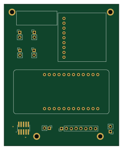
Radar System Layout - Component and Top Cu

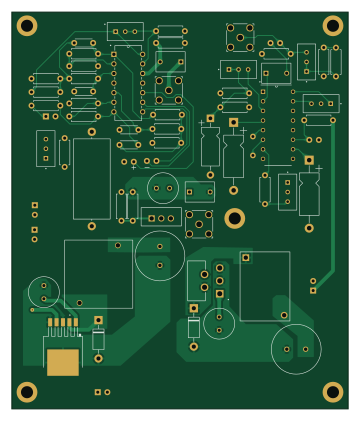
About the Radar System Layout - Component and Top Cu PCB
Radar System Layout - Component and Top Cu is an open source PCB design by ocm87, published on GitHub under the MIT license. It is a 4-layer board measuring 89 × 105 mm, with 67 components from 40 distinct parts.
Other key parts include the XR2206CP-F, LM2575T-3.3, LT1214CN-PBF, LM317T and LM2575S-5.0/NOPB. By type, the board carries 23 resistors, 17 capacitors, 12 connectors, 5 ICs, 2 diodes and 2 inductors.
From the project
ELEC4907 FMCW Radar Project
Team Members: Carter Livermore, Jin Her, Max Hecht, Owen MacIntosh
Main components on the Radar System Layout - Component and Top Cu
Radar System Layout - Component and Top Cu bill of materials (BOM)
67 components, 40 distinct parts — part numbers from the project's BOM.
| Qty | Part | Footprint | Refs |
|---|---|---|---|
| 1 | XR2206CP-F | DIP794W56P254L2013H533Q16N | IC1 |
| 1 | LM2575T-3.3 | (3v3)TO170P470X1016X2092-5P | U1 |
| 1 | LT1214CN-PBF | PDIP-14_N_LIT | U3 |
| 1 | LM317T | TO-220_STM | U4 |
| 1 | LM2575S-5.0/NOPB | KTT0005B | U5 |
| 1 | ARM_CORTEX_SWD_10 RF2-04A-T-00-50-G | CONN_RF2-04A-T-00-50-G_ADM | J1 |
| 7 | ~ | 2-54mm_Spacing | J2, J5, J6, J8, J9, J11, J12 |
| 2 | RF2-04A-T-00-50-G | CONN_RF2-04A-T-00-50-G_ADM | J3, J10 |
| 1 | 3V3_MCU_JUMP ~ | 2-54mm_Spacing | J4 |
| 1 | 5V_MCU_JUMP ~ | 2-54mm_Spacing | J7 |
| 3 | 100k | TRIM_3296W-1-503LF | DC_ADJUST1, PREAMP_GAIN1, VR1 |
| 2 | 25k | TRIM_3296W-1-503LF | VR2, VR4 |
| 1 | 50k | TRIM_3296W-1-503LF | VR3 |
| 2 | 1N5819 | D_DO-41_SOD81_P10.16mm_Horizontal | D1, D2 |
| 1 | ~ | IND_PE-526xx_V_PUL | L1 |
| 1 | ~ | 330uH Inductor | L2 |
| 3 | 100uF | 100uF_RadialCap | C1, C4, C17 |
| 2 | 330uF | 330uF_radialCap | C2, C3 |
| 3 | 1uF | R82-D_KEM | C5, C13, C16 |
| 1 | 0.47uF | 0.47uF_cap | C6 |
Show 20 more
| Qty | Part | Footprint | Refs |
|---|---|---|---|
| 2 | 1uF | AxialCap_P18 | C7, C8 |
| 1 | 10uF | Cap_P15 | C9 |
| 3 | 100pF | Disc_Cap_P5mm | C10, C11, C12 |
| 1 | 150pF | Disc_Cap_P5mm | C14 |
| 1 | 10uF | Axial_Cap_P25 | C15 |
| 2 | 100k | resistor | R1, R7 |
| 1 | 39k | resistor | R2 |
| 1 | 33k | resistor | R3 |
| 2 | 4.7k | resistor | R4, R5 |
| 2 | 82k | resistor | R6, R14 |
| 4 | 27k | resistor | R8, R10, R12, R13 |
| 2 | 1M | resistor | R9, R17 |
| 1 | 220 | resistor | R11 |
| 1 | 43k | resistor | R15 |
| 2 | 10k | resistor | R16, R19 |
| 1 | 5.6k | resistor | R18 |
| 1 | 560k | resistor | R20 |
| 1 | 1.5k | resistor | R21 |
| 1 | 390 | resistor | R22 |
| 1 | 0 | resistor | R23 |
Radar System Layout - Component and Top Cu design files
The KiCad project lives in the ocm87/fmcw repository on GitHub; these links point at the commit this page was built from.
Radar System Layout - Component and Top Cu: common questions
How big is the Radar System Layout - Component and Top Cu PCB?
The Radar System Layout - Component and Top Cu measures 89 × 105 mm, has 4 copper layers and is 1.6 mm thick.
How many components are on the Radar System Layout - Component and Top Cu?
67 components, from 40 distinct parts, with part numbers taken from the project's own BOM. The full bill of materials is listed on this page.
Where can I download the Radar System Layout - Component and Top Cu design files?
From the ocm87/fmcw repository on GitHub, which has the KiCad layout, the schematic and the BOM; the links under Design files point to each one.
Can I use the Radar System Layout - Component and Top Cu design in my own project?
Yes, under the terms of its MIT license, which ocm87 chose for the repository.