
Map pinned


About the Map pinned PCB
Map pinned is an open source PCB design by OpenLogicEFI, published on GitHub. It is a 2-layer board measuring 17.2 × 14.9 mm, with 5 components from 5 distinct parts.
By type, the board carries 3 capacitors, 1 connector and 1 resistor.
From the project
Hardware is based off an open source project called Speeduino by Josh Stewart.
OpenLogicEFI ECU's are based off an open source project called Speeduino by Josh Stewart. Currently all released boards use official Speeduino firmware. In TunerStudio set to "Board Layout" to "Speeduino 0.4"
- The Official Speeduino Manual, documents and discord are the best places to start.
Map pinned bill of materials (BOM)
5 components, 5 distinct parts — part numbers from the project's BOM.
| Qty | Part | Footprint | Refs |
|---|---|---|---|
| 1 | Conn_01x06 | MapDapter_1x06_P2.54mm_Horizontal | J2 |
| 1 | 47pF | C_0402_1005Metric | C1 |
| 1 | 100nF | C_0402_1005Metric | C2 |
| 1 | 1u | C_0402_1005Metric | C3 |
| 1 | 51k | R_0402_1005Metric | R1 |
Map pinned design files
The KiCad project lives in the OpenLogicEFI/Hardware repository on GitHub; these links point at the commit this page was built from.
Map pinned: common questions
How big is the Map pinned PCB?
The Map pinned measures 17.2 × 14.9 mm, has 2 copper layers and is 1.6 mm thick.
How many components are on the Map pinned?
5 components, from 5 distinct parts, with part numbers taken from the project's own BOM. The full bill of materials is listed on this page.
Where can I download the Map pinned design files?
From the OpenLogicEFI/Hardware repository on GitHub, which has the KiCad layout, the schematic and the BOM; the links under Design files point to each one.
Can I use the Map pinned design in my own project?
The repository has no license, so all rights stay with OpenLogicEFI. Use it as a reference, and ask the author before reusing the design.
More boards in Hardware
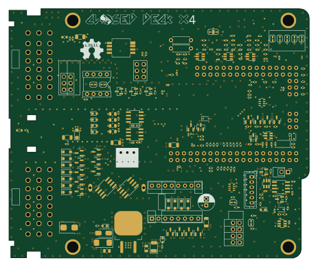
Closed deck x4
115.5 × 96.2 mm212 parts4LNo license18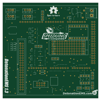 AVR/Arduino
1.3
100 × 100 mm156 partsNo license18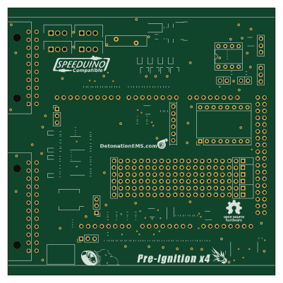 AVR/Arduino
Pre Ignition
100 × 100 mm136 partsNo license18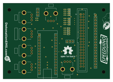 AVR/Arduino
Simulator
97.6 × 70 mm40 parts2LNo license18
Max9926-VR
21.7 × 22.2 mm14 parts2LNo license18
Duel VR
22.9 × 20.1 mm13 parts2LNo license18
ICM
54.1 × 27.4 mm5 parts2LNo license18
Endcap
102.9 × 30.4 mm4 parts2LNo license18