
Receiver

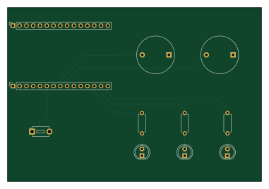
About the Receiver PCB
Receiver is an open source PCB design by p-keminer, published on GitHub under the MIT license. It is a 2-layer board measuring 95 × 65.1 mm, with 11 components from 6 distinct parts.
By type, the board carries 3 diodes, 3 resistors, 2 connectors, 2 buzzers and 1 switch.
It belongs with the iot & wireless designs in this gallery.
From the project
IoT-Basis-Alarmanlage mit ESP8266-Nodes, Elegoo Uno R3, Raspberry Pi Zero 2 W, HMAC-SHA256-Absicherung, eigenen PCBs und 3D-gedruckten Gehäusen. // IoT basic alarm system with ESP8266 nodes, Elegoo Uno R3, Raspberry Pi Zero 2 W, HMAC-SHA256 security, custom PCBs, and 3D-printed housings.
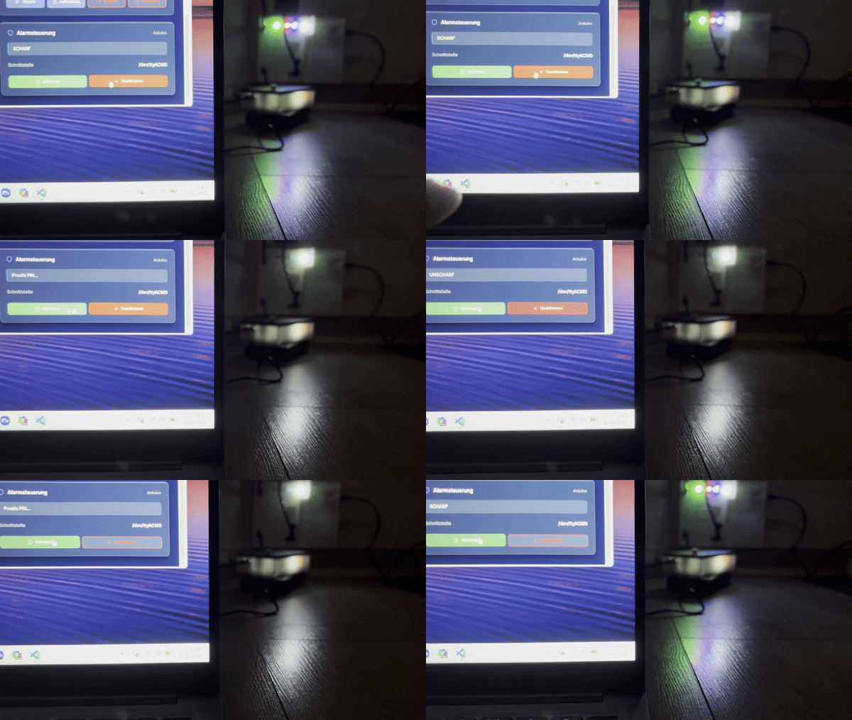
Die IoT-Alarmanlage basiert auf einem Elegoo Uno R3, zwei ESP8266 und einem Raspberry Pi Zero 2 W. RFID und zwei Reed-Sensoren steuern die lokale Alarm-FSM. Ein Funkpfad uebertraegt Alarmzustaende an den Empfaenger; das Dashboard zeigt Telemetrie, Logs und Aufnahmen und sendet freigegebene Befehle.
Dieses Projekt entstand in meinem ersten Studiensemester und war mein erstes Lernprojekt.
Receiver bill of materials (BOM)
11 components, 6 distinct parts.
| Qty | Part | Footprint | Refs |
|---|---|---|---|
| 1 | Links | PinSocket_1x15_P2.54mm_Vertical | J1 |
| 1 | Rechts | PinSocket_1x15_P2.54mm_Vertical | J2 |
| 2 | Buzzer | Buzzer_D14mm_H7mm_P10mm | BZ1, BZ2 |
| 1 | SW_Push | SW_PUSH_1P1T_6x3.5mm_H5.0_APEM_MJTP1250 | SW1 |
| 3 | LED | LED_D5.0mm | D1, D2, D3 |
| 3 | 100 | R_Axial_DIN0207_L6.3mm_D2.5mm_P7.62mm_Horizontal | R1, R2, R3 |
Receiver design files
The KiCad project lives in the p-keminer/iot-alarm-system repository on GitHub; these links point at the commit this page was built from.
Receiver: common questions
How big is the Receiver PCB?
The Receiver measures 95 × 65.1 mm, has 2 copper layers and is 1.6 mm thick.
How many components are on the Receiver?
11 components, from 6 distinct parts. The full bill of materials is listed on this page.
Where can I download the Receiver design files?
From the p-keminer/iot-alarm-system repository on GitHub, which has the KiCad layout and the schematic; the links under Design files point to each one.
Can I use the Receiver design in my own project?
Yes, under the terms of its MIT license, which p-keminer chose for the repository.
More boards in iot-alarm-system
Similar boards
EinkPDA screen
TalismanDesign
95 × 54 mm27 parts2LApache-2.02.0k
RPi RM0 WiFi/Bluetooth Module
schlae
11.1 × 14 mm76 parts6LNo license1.0k
Breakout board
Luos-io
26.7 × 27.9 mm29 parts2LMIT547
Stm32f0 disco Luos shield
55.9 × 99.1 mm26 parts2LMIT547
L0 USB
20.3 × 15.3 mm19 parts2LMIT547
L0 USBA
20.3 × 15.3 mm19 parts2LMIT547