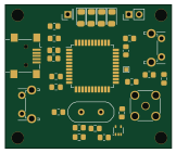
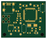
Simulation

About the Simulation PCB
Simulation is an open source PCB design by Pauloux, published on GitHub under the GPL-3.0 license. It is a 2-layer board, with 14 components from 13 distinct parts.
By type, the board carries 7 capacitors, 2 inductors and 2 resistors.
From the project
Projet du cours ATCE portant sur l'asservissement d'un oscillateur à quartz
Simulation bill of materials (BOM)
14 components, 13 distinct parts — part numbers from the project's BOM.
| Qty | Part | Footprint | Refs |
|---|---|---|---|
| 2 | ${SIM.PARAMS} | B1, B2 | |
| 1 | ESOURCE | E1 | |
| 1 | 10U 10u | L_0805_2012Metric_Pad1.05x1.20mm_HandSolder | L1 |
| 1 | 5m | L2 | |
| 1 | 15P 7p | C_0805_2012Metric_Pad1.18x1.45mm_HandSolder | C1 |
| 1 | 10U 1u | C_1206_3216Metric_Pad1.33x1.80mm_HandSolder | C5 |
| 1 | 10U 19.78929368f | C6 | |
| 1 | 10U 10p | C_0805_2012Metric_Pad1.18x1.45mm_HandSolder | C8 |
| 1 | 10U 15p | C_0805_2012Metric_Pad1.18x1.45mm_HandSolder | C9 |
| 1 | 10U 1u | C_0805_2012Metric_Pad1.18x1.45mm_HandSolder | C10 |
| 1 | 2p | C_0805_2012Metric_Pad1.18x1.45mm_HandSolder | C11 |
| 1 | 50 | R1 | |
| 1 | 5k | R_0805_2012Metric_Pad1.20x1.40mm_HandSolder | R5 |
Simulation design files
The KiCad project lives in the Pauloux/Projet-ATCE repository on GitHub; these links point at the commit this page was built from.
Simulation: common questions
How big is the Simulation PCB?
The Simulation has 2 copper layers and is 1.6 mm thick.
How many components are on the Simulation?
14 components, from 13 distinct parts, with part numbers taken from the project's own BOM. The full bill of materials is listed on this page.
Where can I download the Simulation design files?
From the Pauloux/Projet-ATCE repository on GitHub, which has the KiCad layout, the schematic and the BOM; the links under Design files point to each one.
Can I use the Simulation design in my own project?
Yes, under the terms of its GPL-3.0 license, which Pauloux chose for the repository.