
Panasonic wv cm2080-rgb mux

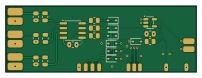
About the Panasonic wv cm2080-rgb mux PCB
Panasonic wv cm2080-rgb mux is an open source PCB design by pcm720, published on GitHub under the CERN-OHL-W-2.0 license. It is a 2-layer board measuring 50.5 × 17.5 mm, with 38 components from 24 distinct parts.
Other key parts include the THS7314 and 74LVC1G08. By type, the board carries 17 connectors, 7 diodes, 7 resistors, 5 capacitors and 2 ICs.
From the project
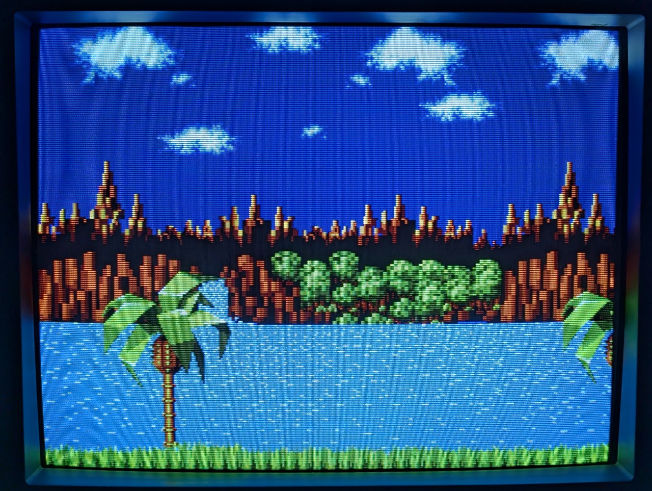
RGB Mux mod for Panasonic WV-CM1480/1780/2080 CRT TVs
The TV only has two composite inputs and one S-Video input, but can be relatively easily modded for RGB while keeping the other two inputs functional.
The regular RGB mux method cannot be used on these TVs because - The AN5192K jungle IC doesn’t have dedicated RGB inputs and expects a non-standard input signal up to 2.5V on its OSD RGB lines - The OSD input uses a single microprocessor output (OSD B out) that's wired to all three RGB inputs (R, G, B) via a buffer transistor
Main components on the Panasonic wv cm2080-rgb mux
Panasonic wv cm2080-rgb mux bill of materials (BOM)
38 components, 24 distinct parts.
| Qty | Part | Footprint | Refs |
|---|---|---|---|
| 1 | THS7314 | SOIC-8_3.9x4.9mm_P1.27mm | U1 |
| 1 | 74LVC1G08 | SOT-23-5 | U2 |
| 1 | R_IN | SolderWirePad_1x01_SMD_2x4mm | J1 |
| 1 | R_GND | SolderWirePad_1x01_SMD_2x4mm | J2 |
| 1 | G_IN | SolderWirePad_1x01_SMD_2x4mm | J3 |
| 1 | G_GND | SolderWirePad_1x01_SMD_2x4mm | J4 |
| 1 | B_IN | SolderWirePad_1x01_SMD_2x4mm | J5 |
| 1 | B_GND | SolderWirePad_1x01_SMD_2x4mm | J6 |
| 1 | OSD_B_IN | SolderWirePad_1x01_SMD_1x2mm | J7 |
| 1 | R_OUT | SolderWirePad_1x01_SMD_1x2mm | J8 |
| 1 | G_OUT | SolderWirePad_1x01_SMD_1x2mm | J9 |
| 1 | B_OUT | SolderWirePad_1x01_SMD_1x2mm | J10 |
| 1 | 5V | SolderWirePad_1x01_SMD_1x2mm | J11 |
| 1 | GND | SolderWirePad_1x01_SMD_1x2mm | J12 |
| 1 | AB_IN | SolderWirePad_1x01_SMD_1.5x3mm | J13 |
| 1 | VS_IN | SolderWirePad_1x01_SMD_1.5x3mm | J14 |
| 1 | BL_OUT | SolderWirePad_1x01_SMD_1x2mm | J15 |
| 1 | OSD_R_IN | SolderWirePad_1x01_SMD_1x2mm | J16 |
| 1 | OSD_G_IN | SolderWirePad_1x01_SMD_1x2mm | J17 |
| 7 | 1N4148WS | D_SOD-323 | D1, D2, D3, D4, D5, D6, D7 |
Show 4 more
| Qty | Part | Footprint | Refs |
|---|---|---|---|
| 5 | 0.1uF | C_0805_2012Metric | C1, C2, C3, C4, C5 |
| 3 | 75 | R_0805_2012Metric | R1, R2, R3 |
| 3 | 100 | R_0805_2012Metric | R4, R5, R6 |
| 1 | 330 | R_0805_2012Metric | R7 |
Panasonic wv cm2080-rgb mux design files
The KiCad project lives in the pcm720/panasonic-wv-cm2080-rgb-mux repository on GitHub; these links point at the commit this page was built from.
- Layoutpcb/panasonic-rgbamp.kicad_pcb
- Schematicpcb/panasonic-rgbamp.kicad_sch
Panasonic wv cm2080-rgb mux: common questions
How big is the Panasonic wv cm2080-rgb mux PCB?
The Panasonic wv cm2080-rgb mux measures 50.5 × 17.5 mm, has 2 copper layers and is 1.6 mm thick.
How many components are on the Panasonic wv cm2080-rgb mux?
38 components, from 24 distinct parts. The full bill of materials is listed on this page.
Where can I download the Panasonic wv cm2080-rgb mux design files?
From the pcm720/panasonic-wv-cm2080-rgb-mux repository on GitHub, which has the KiCad layout and the schematic; the links under Design files point to each one.
Can I use the Panasonic wv cm2080-rgb mux design in my own project?
Yes, under the terms of its CERN-OHL-W-2.0 license, which pcm720 chose for the repository.