
Canfw

About the Canfw PCB
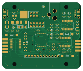
Canfw is an open source PCB design by PDXostc, published on GitHub under the MPL-2.0 license. It is a 2-layer board measuring 68 × 58 mm, with 65 components from 30 distinct parts.
Other key parts include the AT32UC3C, FT232RL-SSOP, MC78M05CDT, SMF05 and MCP25625. By type, the board carries 21 resistors, 14 capacitors, 9 connectors, 6 ICs, 6 diodes and 3 fuses.
From the project
CAN Firewall project
There are two tables, IVI2VEH and VEH2IVI, specifiying rules for traffic going from the IVI to the vehicle and from vehicle to IVI.
Each one of the two tables has a number of rules.
Each rule has a numberic ID. Rules are executed in order of ascending IDs.
Each rule has an Frame ID mask and a Frame ID filter, applied according to the standard CAN bus filter principle, as described here.
Main components on the Canfw
Canfw bill of materials (BOM)
65 components, 30 distinct parts — part numbers from the project's BOM.
| Qty | Part | Footprint | Refs |
|---|---|---|---|
| 1 | AT32UC3C | LQFP-64_10x10mm_Pitch0.5mm | U1 |
| 1 | FT232RL-SSOP | SSOP-28_5.3x10.2mm_Pitch0.65mm | U2 |
| 1 | MC78M05CDT | D-Pak_TO252AA | U3 |
| 1 | SMF05 | SC-70-6 | U4 |
| 2 | MCP25625 | SSOP-28_5.3x10.2mm_Pitch0.65mm | U5, U6 |
| 1 | TXC | TXC | X1 |
| 1 | BARREL_JACK | RAPC722X | CON1 |
| 1 | AVR-JTAG-10 | Socket_Strip_Straight_2x05 | CON2 |
| 1 | AVR-AW-6 | Socket_Strip_Straight_2x03 | CON3 |
| 1 | +5V_SRC | Socket_Strip_Straight_1x03 | J1 |
| 2 | DB9 | DB9F_CI | J2, J3 |
| 2 | USB_OTG | USB_Micro-B-DX4R005JJ2R1800 | P1, P2 |
| 1 | DIAG Port | Socket_Strip_Straight_1x12 | P3 |
| 3 | FUSE | R_1210_SM | F1, F2, F3 |
| 3 | SPST | SW_SPST_FSMSM_SM | SW1, SW2, SW3 |
| 1 | YELLOW | Diode_0805_12 | D1 |
| 1 | WHITE | Diode_0805_12 | D2 |
| 1 | SMBJ16A | SMB_Standard | D3 |
| 1 | RED | Diode_0805_12 | D4 |
| 1 | GREEN | Diode_0805_12 | D5 |
Show 10 more
| Qty | Part | Footprint | Refs |
|---|---|---|---|
| 1 | BLUE | Diode_0805_12 | D6 |
| 2 | 220 | Diode_0805_12_SM | FB1, FB2 |
| 3 | 10N | R_0603_sm | C1, C2, C6 |
| 10 | 100N | R_0603_sm | C3, C4, C5, C8, C9, C10, C11, C12 +2 |
| 1 | 47U | TantalC_SizeA_EIA-3216_Reflow | C7 |
| 3 | 22 | R_0603_sm | R1, R2, R3 |
| 11 | 470 | R_0603_sm | R4, R5, R6, R7, R8, R10, R11, R12 +3 |
| 1 | 4K7 | R_0603_sm | R9 |
| 4 | 0 | R_0603_sm | R16, R17, R18, R19 |
| 2 | 120 | R_0603_sm | R20, R21 |
Canfw design files
The KiCad project lives in the PDXostc/canfw repository on GitHub; these links point at the commit this page was built from.
Canfw: common questions
How big is the Canfw PCB?
The Canfw measures 68 × 58 mm, has 2 copper layers and is 1.6 mm thick.
How many components are on the Canfw?
65 components, from 30 distinct parts, with part numbers taken from the project's own BOM. The full bill of materials is listed on this page.
Where can I download the Canfw design files?
From the PDXostc/canfw repository on GitHub, which has the KiCad layout and the BOM; the links under Design files point to each one.
Can I use the Canfw design in my own project?
Yes, under the terms of its MPL-2.0 license, which PDXostc chose for the repository.