
SparkFun GPS NEO M9N SMA

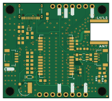
About the SparkFun GPS NEO M9N SMA PCB
SparkFun GPS NEO M9N SMA is an open source NXP PCB design by PHS-SMCS, published on GitHub. It is a 2-layer board measuring 40.6 × 36.8 mm, with 88 components from 67 distinct parts.
Its main chip is the TEENSY4.1, from the NXP family. Other key parts include the URB4805LD-30WR3_C20199272. By type, the board carries 44 ICs, 16 resistors, 6 jumpers, 5 connectors, 5 capacitors and 2 LEDs.
It belongs with the rf & radio, robotics & motion and sensors designs in this gallery.
From the project
Documentation for the SMCSKart PCB
Custom PCB integrating every system in the SMCS Robotics 8th period go-kart. The board acts as the central hub between a Raspberry Pi 4, a Teensy 4.1, all motor controller I/O, sensors, and peripherals.
The board supplies three voltage rails available on the extra power port:
All toggle output pins drive an IRLZ44N MOSFET with a pulldown resistor, providing an active-low ground signal to the ESC connector.
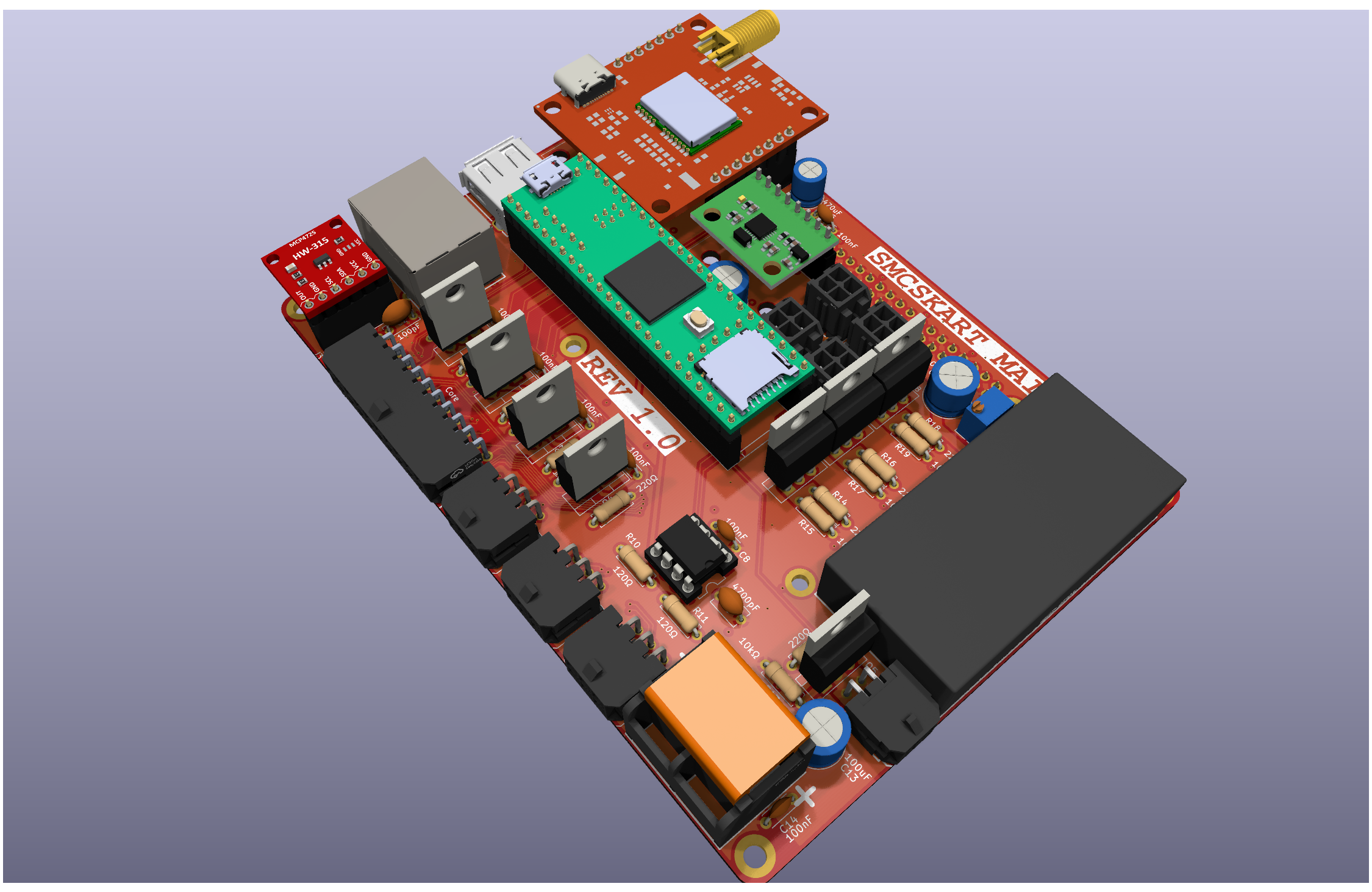
Main components on the SparkFun GPS NEO M9N SMA
SparkFun GPS NEO M9N SMA bill of materials (BOM)
88 components, 67 distinct parts — part numbers from the project's BOM.
| Qty | Part | Footprint | Refs |
|---|---|---|---|
| 1 | TEENSY4.1 U-BLOX_NEO-M9N | NEO-M9N_M8T_M8U | U1 |
| 1 | URB4805LD-30WR3_C20199272 3.3V | SOT23-5 | U2 |
| 1 | — | ##CS##9 | U$1 |
| 1 | — | U#BLOX19 | U$2 |
| 1 | — | ##SAFE##15 | U$3 |
| 4 | — | #3V3#6 | U$4, U$5, U$39, U$40 |
| 2 | — | #5V#1 | U$6, U$42 |
| 4 | — | #GND#0 | U$7, U$8, U$38, U$41 |
| 1 | — | #INT#16 | U$9 |
| 1 | — | PPS7 | U$10 |
| 2 | — | #PPS#13 | U$11, U$32 |
| 1 | — | #SPI#22 | U$12 |
| 1 | — | PWR6 | U$13 |
| 1 | — | QWIIC_4MM | U$14 |
| 1 | — | #RX#SDI#10 | U$15 |
| 1 | — | #SCK#12 | U$16 |
| 1 | — | #PWR#1 | U$17 |
| 1 | — | #SCL#18 | U$18 |
| 1 | — | #SDA#17 | U$19 |
| 1 | — | #TX#SDO#11 | U$20 |
Show 47 more
| Qty | Part | Footprint | Refs |
|---|---|---|---|
| 1 | — | NEO_GPS_BOARD_SILK_FINAL#03#JPG | U$21 |
| 1 | — | ##SAFE##11 | U$22 |
| 1 | — | L1#L28 | U$23 |
| 1 | — | ANT8 | U$24 |
| 1 | — | NEO#M9N20 | U$25 |
| 1 | — | ##CS##6 | U$26 |
| 1 | — | ##RST##12 | U$27 |
| 1 | — | ##RST##2 | U$28 |
| 1 | — | #I2C#3 | U$29 |
| 1 | — | #INT#10 | U$30 |
| 1 | — | #PPS#0 | U$31 |
| 1 | — | #RX#SDI#4 | U$33 |
| 1 | — | #SCK#3 | U$34 |
| 1 | — | #SCL#8 | U$35 |
| 1 | — | #SDA#9 | U$36 |
| 1 | — | #TX#SDO#5 | U$37 |
| 1 | RASPBERRY_PI_4 | 1X07_NO_SILK | J1 |
| 1 | Qwiic Right Angle | JST04_1MM_RA | J2 |
| 1 | MCP4275_BREAKOUT | USB-C-16P-2LAYER-PADS | J3 |
| 1 | 0430450400 Qwiic Right Angle | JST04_1MM_RA | J4 |
| 1 | C7541613 TRANCIEVER | 1X04_NO_SILK | J5 |
| 1 | 6.8MM_COIN_CELL | ML414H_IV01E | B1 |
| 1 | ANTENNA-GROUNDEDEDGE_SMA_SMD | SMA-EDGE-SMD | E1 |
| 1 | FRAME-LETTER | CREATIVE_COMMONS | FRAME1 |
| 4 | STAND-OFF | STAND-OFF | JP1, JP31, JP91, JP101 |
| 1 | JUMPER-SMT_3_2-NC_TRACE_SILK | SMT-JUMPER_3_2-NC_TRACE_SILK | JP5 |
| 1 | — | 1X04_NO_SILK | JP15 |
| 2 | JUMPER-SMT_2_NC_TRACE_SILK | SMT-JUMPER_2_NC_TRACE_SILK | PPS0, PWR\0 |
| 1 | JUMPER-SMT_2_NO_SILK | SMT-JUMPER_2_NO_SILK | SPI0 |
| 1 | TEST-POINT3X4 | PAD.03X.04 | TP1 |
| 1 | BLUE | LED-0603 | LED1 |
| 1 | RED | LED-0603 | LED2 |
| 1 | 0.5A/40V/420mV | SOD-323 | D2 |
| 1 | PRTR5V0U2F | SOT886 | D3 |
| 1 | FERRITE_BEAD-120_OHM-0402 | 0402 | FB1 |
| 1 | 100NF 47pF | 0402 | C1 |
| 2 | 100NF 1.0uF | 0603 | C3, C4 |
| 1 | 100NF 0.1uF | 0603 | C5 |
| 1 | 4700PF 1.0uF | 0603 | C6 |
| 3 | 1k | 0603 | R1, R5, R11 |
| 4 | 33 | 0603 | R2, R3, R4, R6 |
| 2 | 2.2k | 0603 | R7, R8 |
| 2 | 27 | 0603 | R9, R10 |
| 2 | 5.1k | 0603 | R12, R13 |
| 1 | 33 | 0402 | R14 |
| 1 | 100k | 0603 | R15 |
| 1 | 10k | 0402 | R16 |
SparkFun GPS NEO M9N SMA design files
The KiCad project lives in the PHS-SMCS/SMCSKart-Mainboard repository on GitHub; these links point at the commit this page was built from.
SparkFun GPS NEO M9N SMA: common questions
What microcontroller does the SparkFun GPS NEO M9N SMA use?
The SparkFun GPS NEO M9N SMA is built around the TEENSY4.1, from the NXP family.
How big is the SparkFun GPS NEO M9N SMA PCB?
The SparkFun GPS NEO M9N SMA measures 40.6 × 36.8 mm, has 2 copper layers and is 1.6 mm thick.
How many components are on the SparkFun GPS NEO M9N SMA?
88 components, from 67 distinct parts, with part numbers taken from the project's own BOM. The full bill of materials is listed on this page.
Where can I download the SparkFun GPS NEO M9N SMA design files?
From the PHS-SMCS/SMCSKart-Mainboard repository on GitHub, which has the KiCad layout, the schematic and the BOM; the links under Design files point to each one.
Can I use the SparkFun GPS NEO M9N SMA design in my own project?
The repository has no license, so all rights stay with PHS-SMCS. Use it as a reference, and ask the author before reusing the design.
Can I test firmware for the SparkFun GPS NEO M9N SMA without the hardware?
Yes. HardLabs builds a simulation of the board from its netlist and BOM, so you can run and debug NXP firmware against it before you order a PCB.
More boards in SMCSKart-Mainboard
Similar boards
 NXP
32Bit shift register
MaltWhiskey
100 × 54 mm56 parts4LNo license763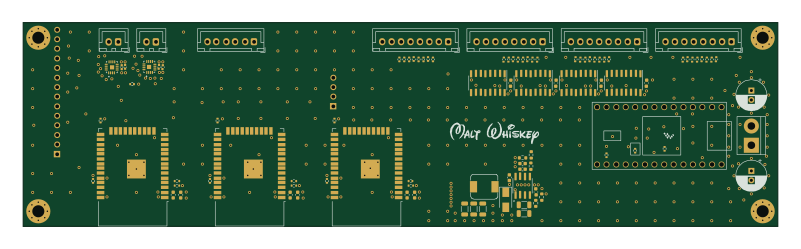 NXP
Mega-Cube-Board
200 × 54 mm100 parts4LNo license763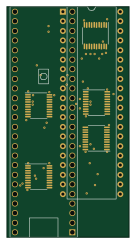 NXP
MCL6809
MicroCoreLabs
32.3 × 61 mm7 parts4LNo license532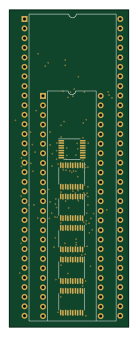 NXP
MCL68
31.6 × 84.1 mm13 parts4LNo license532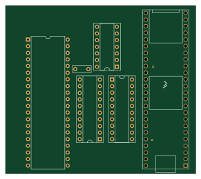 NXP
MCL65+
72.6 × 64.1 mm6 parts2LNo license532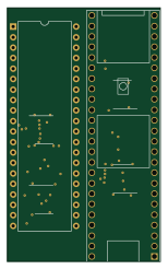 NXP
MCLZ8
37.1 × 61.5 mm6 parts4LNo license532