
Romi board

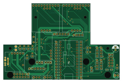
About the Romi board
Romi board is an open source NXP PCB design by portlandrobotics, published on GitHub under the SHL-2.1 license. It is a 2-layer board measuring 107 × 70 mm, with 41 components from 25 distinct parts.
Its main chip is the MCP1703A-5002_SOT23, from the NXP family. By type, the board carries 9 resistors, 7 jumpers, 4 connectors, 2 transistors, 2 switches and 2 capacitors.
It belongs with the robotics & motion and power & battery designs in this gallery.
From the project
- In general, follow the instructions in the Romi chassis assembly guide. Note that wheel encoders should be installed as shown in those instructions and will plug into the bottom board. - The interactive BOM is helpful while soldering components onto the board. - We recommend us
- In general, follow the instructions in the Romi chassis assembly guide. Note that wheel encoders should be installed as shown in those instructions and will plug into the bottom board. - The interactive BOM is helpful while soldering components onto the board. - We recommend using headers between the boards so that disassembly is possible. Use female (socket) header on the bottom board and male (pin) headers on top board. Pin headers come with all of the breakout boards. - Use the top board to guide breakout board header soldering. Insert the pin headers into the appropriate positions on…
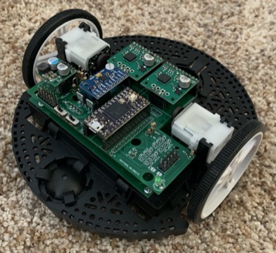
Main components on the Romi board
Romi board bill of materials (BOM)
41 components, 25 distinct parts — part numbers from the project's BOM.
| Qty | Part | Footprint | Refs |
|---|---|---|---|
| 1 | MCP1703A-5002_SOT23 Teensy4.0 | Teensy40_simple | U1 |
| 2 | Q_PMOS_DGS | TO-251-3_Vertical | Q1, Q2 |
| 2 | CONN_01X03 Conn_01x14 | PinHeader_1x14_P2.54mm_Vertical | J1, J2 |
| 1 | CONN_01X04 Conn_02x06_Odd_Even | PinHeader_2x06_P2.54mm_Vertical | J3 |
| 1 | CONN_01X06 USB_B_Micro | USB_Micro-B_Molex_47346-0001 | J4 |
| 1 | Conn_01x06 | PinHeader_1x06_P2.54mm_Vertical | C_IBC_L1 |
| 1 | Conn_01x04 | PinHeader_1x02_P2.54mm_Vertical | C_IBC_R1 |
| 1 | Conn_01x07 | PinHeader_1x06_P2.54mm_Vertical | C_IBC_T1 |
| 2 | TB9051FTG | TB9051FTG_db | DRV_LEFT1, DRV_RIGHT1 |
| 5 | Conn_01x04 | PinHeader_1x04_P2.54mm_Vertical | I2C_ACC1, I2C_ACC2, I2C_ACC3, I2C_ACC4, ULTRASONIC1 |
| 1 | Conn_01x04 | MPU9250_BB | IMU-9250 |
| 5 | SolderJumper_2_Open | SolderJumper-2_P1.3mm_Open_RoundedPad1.0x1.5mm | JP1, JP2, JP3, JP6, JP7 |
| 2 | SolderJumper_2_Bridged | SolderJumper-2_P1.3mm_Bridged_RoundedPad1.0x1.5mm | JP4, JP5 |
| 1 | RASPBERRY_PI_GPIO | PinHeader_2x05_P2.54mm_Vertical | PI1 |
| 1 | D24V22F5 | D24V2F5_bb | REG_5V1 |
| 2 | SW_SPDT | Switch | SW1, SW2 |
| 1 | LED | LED_D5.0mm | D1 |
| 1 | 2.2U 0.1u | C_Disc_D5.0mm_W2.5mm_P5.00mm | C1 |
| 1 | 100N 470u | CP_Radial_D6.3mm_P2.50mm | C2 |
| 1 | 330K 2M | R_Axial_DIN0309_L9.0mm_D3.2mm_P2.54mm_Vertical | R1 |
Show 5 more
| Qty | Part | Footprint | Refs |
|---|---|---|---|
| 1 | 1M | R_Axial_DIN0309_L9.0mm_D3.2mm_P2.54mm_Vertical | R2 |
| 1 | 4.7K 1K | R_Axial_DIN0309_L9.0mm_D3.2mm_P2.54mm_Vertical | R3 |
| 2 | 4.7K | R_Axial_DIN0309_L9.0mm_D3.2mm_P2.54mm_Vertical | R4, R5 |
| 1 | 3.3K | R_Axial_DIN0309_L9.0mm_D3.2mm_P2.54mm_Vertical | R6 |
| 3 | 10K 4.7K | R_Axial_DIN0309_L9.0mm_D3.2mm_P2.54mm_Vertical | R7, R8, R9 |
Romi board design files
The KiCad project lives in the portlandrobotics/common_platform repository on GitHub; these links point at the commit this page was built from.
Romi board: common questions
What microcontroller does the Romi board use?
The Romi board is built around the MCP1703A-5002_SOT23, from the NXP family.
How big is the Romi board?
The Romi board measures 107 × 70 mm, has 2 copper layers and is 1.6 mm thick.
How many components are on the Romi board?
41 components, from 25 distinct parts, with part numbers taken from the project's own BOM. The full bill of materials is listed on this page.
Where can I download the Romi board design files?
From the portlandrobotics/common_platform repository on GitHub, which has the KiCad layout, the schematic and the BOM; the links under Design files point to each one.
Can I use the Romi board design in my own project?
It is published under SHL-2.1, which limits how it may be reused; read the license before building on it.
Can I test firmware for the Romi board without the hardware?
Yes. HardLabs builds a simulation of the board from its netlist and BOM, so you can run and debug NXP firmware against it before you order a PCB.
More boards in common_platform
Similar boards
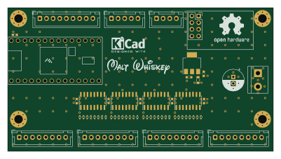 NXP
32Bit shift register
MaltWhiskey
100 × 54 mm56 parts4LNo license763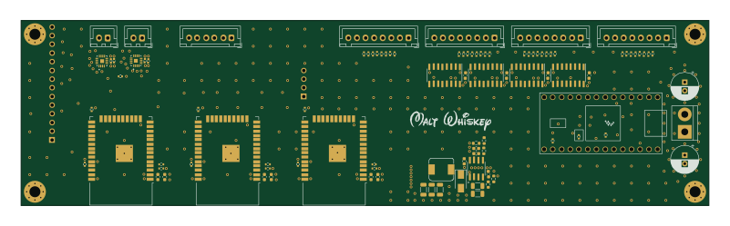 NXP
Mega-Cube-Board
200 × 54 mm100 parts4LNo license763 NXP
MCL6809
MicroCoreLabs
32.3 × 61 mm7 parts4LNo license532 NXP
MCL68
31.6 × 84.1 mm13 parts4LNo license532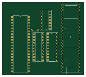 NXP
MCL65+
72.6 × 64.1 mm6 parts2LNo license532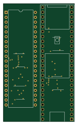 NXP
MCLZ8
37.1 × 61.5 mm6 parts4LNo license532